There is no visible difference. After testing with pins 8 & 6 jumped I get the same amps as before (1.1 Amps and change).
I pulled the zener diode off. There is no change with it off the board. Still get 1.1 amp.
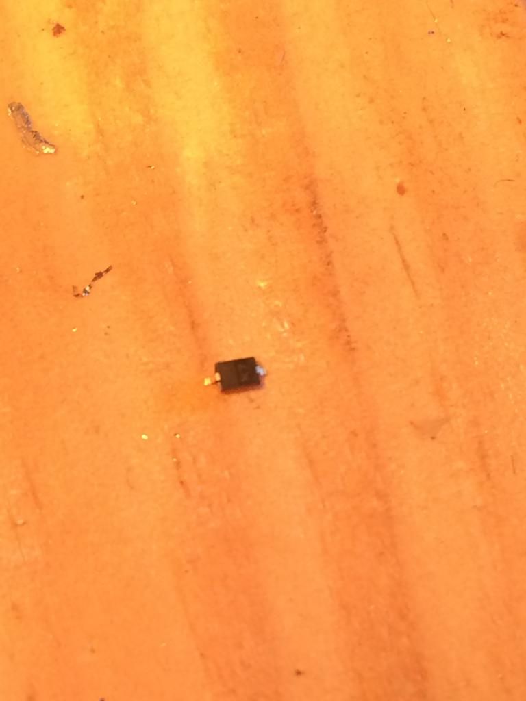
Can someone tell me the correct orientation for this new diode?
Heh, that’s a bad thing to do. Do not attempt to run the board without a Zener. It is likely that you will damage the MCU as the Absolute Maximum Rating for that pin (Vcc) is 6.0v. The MCU should be operated between 1.8v and 5.5v only.
EDIT: Also, the absolute maximum rating for the Vdd pin (PWM pin) on a 7135 is 7v.
Pardon my stupidity, but this driver is designed for a momentary only switch. How can it work right without one?
Oh, I ran one without a zener, don't do it, I fried an mcu that way. Just testing the limits...
It’s fine for an ontime firmware. Momentary firmwares use the same hardware as regular ontime firmware drivers.
“ontime” firmwares change their behavior based on how long they’ve been “on” (eg how long ago you applied power). “momentary” firmwares change their behavior based on an extra input.
Yes. I just wondered if the mcu being one for clicky, would the pin configuration be different, compare to how the board is configured, so that it wasn't changing modes and just hung on one mode?
Where possible we use the same pinout for everything, it’s pin-compatible with Qlite and Nanjg-105c programmed MCUs.
Now if this was an MCU flashed with an offtime firmware and was installed on this PCB with no cap air-wired between the SW+ pad and GND… then it would be stuck in one mode. The only difference in pinout between the 3 major styles of firmware is the use of Pin2:
ontime (Qlite, Nanjg, STAR-ontime, etc): Pin2 is unused
offtime (STAR-offtime, BLF-VLD w/ offtime, etc): Pin2 is attached to a capacitor
momentary (STAR-momentary, some DrJones, etc): Pin2 is attached to a button
Since the MCU was transplanted from a Qlite it simply ignores Pin2.
Just asked because the board was designed specifically for the DrJones lumodrv firmware, that's all.
GulfCoast, any headway on the build?
I replaced the Zener with a new one and nothing changed. Next I added two more 7135’s and to my surprise the amps rose accordingly. I’m thinking maybe I’m overheating the 7135’s when I add them to the board and possibly destroying them. My next step is to start replacing them one at a time.
I had good luck when stacking chips on a qlite. This is my first attempt to add them straight to the board.
Interesting. I haven’t had much trouble with that (eg none that I know of). I’ve torn several 7135 apart while soldering, but that’s always been pretty obvious.
EDIT: FWIW stacking has always been harder for me than soldering or desoldering 7135’s from a PCB.
Are you doing hot air reflow or are you soldering? If it's soldering, you might not be getting all three legs contacting properly. Cold joints are an issue when trying to solder with an iron, on a large board. The way I check all my chips is with an ohm meter set on the 2m setting. Looking at the three legs facing me, I check the left leg to the middle leg and then the middle leg to the right leg. I have found bad chips that way. I normally get 264 for a reading from the left to middle leg and 048 from the middle leg to the right leg and when one is weak, the numbers change a lot, so it's suspect and when they are bad, it's an open circuit. All I really look for is consistent numbers from all the chips. Different runs of them will be a little different reading, but consistency is what I look at. I check them after I have soldered them on. I imagine the gurus might say it doesn't work, but I have checked output on ones I thought bad and they either read low amps or open, so it seems to work.
However I think I’m going to drive over to fry’s electronics this morning and buy this gun http://www.frys.com/product/6471212 that looks similar to what Tom E suggested in one of his threads. They also have soldering paste at fry’s. Then I’ll give hot air reflow a shot. It couldn’t be worse than my soldering!
I started fresh with a new board. This time I left the MCU off and jumped pins 6 & 8 with a wire. I added one 7135 at a time and then bench tested with a MT-G2 to make sure the amps increased accordingly. That part went rather well. Then I added the lumodrv MCU and tested it on the bench with a momentary switch. That’s when the new problem starts. I can turn the light on and ramp up but when I let go of the switch the led ramps down slowly until it is off. I thought it was possibly the switch so I took it off and then used a wire to jump from the + switch pad to the ground. When I take the wire off it still ramps down.
Does tapping work correctly? Tapping should switch through fixed modes.
Tapping will turn on the light and cycle through levels but once the level is set it ramps back down. I wonder if I can get a video on here.
Your description is clear enough I think.
After you tap into a mode, such as High, what happens if you move the switch+ wire over and hold it against Pin8 (Vcc)?
I turned it on high and immediately went to pin eight with the open end of the + switch wire and it still ramps down.
I really appreciate everyone’s help so far.
When the light ramps up or down on it's own, you have a short which acts as the switch being held down, (acts as a complete circuit). You probably have solder bridging, (bridging across two pins, or bridging to ground), somewhere in the circuit, either on one of the the MCU pins, or the switch. I have been this route and it's why I went to hot air reflow. I also went to using just a tiny bit of solder on every joint, so you could hardly tell it was there at all.
You have one side of the switch to ground and the other side of the switch to the SW pad? and it would ramp on it's own?