So far I have 17 7135’s on it and I’m only getting 1.1 amps at the tailcap. All the modes are working correctly. Every time I add a 7135 the amps stay the same. I’ve started replacing the resistors one by one and I guess I change the zener diode next.
That’s a tried and true board design by many folks here (most notably O-L) so it has to be something on your end, can you tell us about the rest of the setup? Also are you running this from an MCU for testing or just pulling the VCC leg of the 7135’s high to enable?
Host, cell(s), emitter(s), all the details please…
The problem is me for sure! I ordered 3 of these boards but I only had 2 MCU’s with the Dr Jones program on it. For this extra board I used a MCU from a Qlite driver. The setup is very similar to O-L’s Maglite twins build only without the momentary switch since the Qlite MCU did not use one. I’m using effest 26650 batteries. The same batteries in another MT-G2 Maglite mod will pull around 5 amps on my DMM.
There needs to be a sticky about this because it comes up every day ("Why are my current readings low?"). What kind of leads are you using to measure this? I'll bet that they are the stock meter's skinny leads.
Edit: I missed the part where you said you tested 5A with the same DMM. Is the rest of your measuring setup the same? Something seems very wrong to only measure 1.1A.
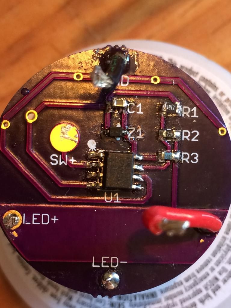
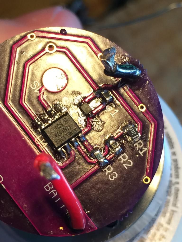
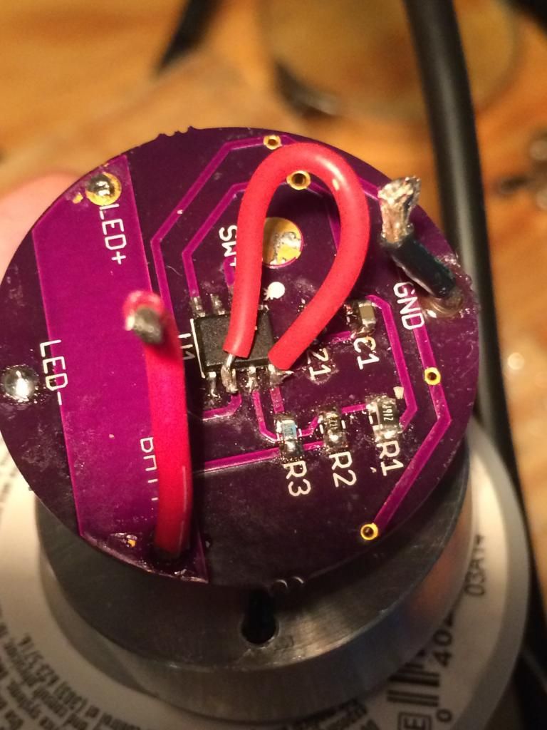
Connect Pin8 (wired to R3 and Z1) of the MCU to Pin6 of the MCU (wired to the 7135’s). At that point the MCU is optional - as long as 8 and 6 are connected on the PCB you do not need the MCU, but it doesn’t hurt anything.
EDIT: Thanks for posting pics - that makes it easier to help!
My multi meter is a Inova 3320 with stock leads.
Batteries are Efest 26650 35000 mah
I have similiar maglite 2D mods that pull around 5-6 amps on the same meter. I’m not too caught up in trying to get an exact amperage per 7135. I just want it to be as bright as the other mods. The other successful mods I have done had the Qlite driver with stacked chips. This is my first attempt at an oshpark build.
Are you measuring through the Maglite switch? Stock tailcap spring? There are a lot of possible places to add resistance and it only takes a little bit to drop a lot of current with an LED.
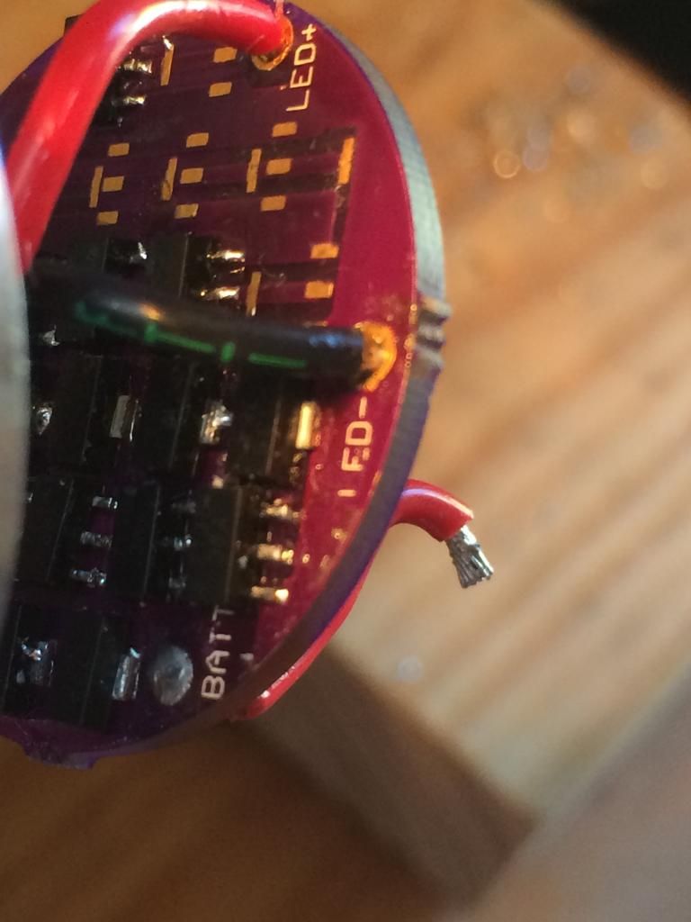
I was measuring through the maglite switch at first with a braid modded spring. Now I have the pill out of the flashlight and I’m measuring directly to the short battery and ground leads.
 Is the rest of your measuring setup the same? Something seems very wrong to only measure 1.1A.