[EDIT: The measured current may be partly or completely wrong by far, so just take it with a grain of salt.]
Hi,
here are some results of LED current depending on PWM value when programming the ATTiny13A (Nanjg, Qlite). I used JonnyC’s STAR firmware for the tests, it should apply to other firmware projects. Results change considerably with PWM frequency, so I added some alternatives.
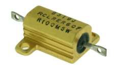
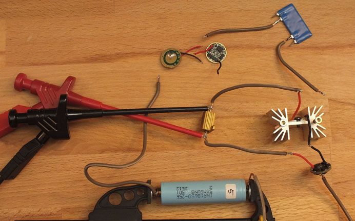
It was all done with a full Samsung INR18650-25R cell and an XM-L U2 1C. Current is calculated by measuring the voltage drop over a 0.1 Ohm shunt, soldered with thick wires between driver and LED. I verified some higher values with a 0.01 Ohm, just in case.
I have by no means a high grade equipment, so we’re not talking scientific precision here (2 mA mean 0.2 mV V-drop). So the lower region is prone to some error. But the values look valid enough for practical use.
I started with the Nanjg 105C, the Nanjg 101-AK-A1 and the Nanjg AK-47A, recently bought from Fasttech. I flashed the STAR (on-time) firmware v. 1.1 with stock frequency 4.8 MHz / fastPWM, resulting in roughly 18 kHz PWM. No surprise here, the 4x driver gives about 4/8 of the 8x driver, except for the low end. Similar results for the 3x driver.
I changed the frequency for the Nanjg 105C then, including ~9kHz which DrJones uses in some firmware (4.8 MHz / PhaseCorrectPWM) and a quite low ~150 Hz (still 4.8 MHz / fastPWM, but with prescaler /64 (TCCR0B = 0x03 instead of 0x01), so it’s 1/64th of the frequency). Results show a great difference in output at lower values.
These current values only result from a full cell and decrease with cell voltage. The driver is dropping out of regulation fast, as stated by HKJ for the 18 kHz Qlite driver. At a resting voltage of 3.8 V the Samsung INR18650-25R already gives a clearly lower output at low and mid PWM values. With a full cell the values are the same with an XM-L2 T6 1A.
I was under the impression that measuring current in this way when there was PWM on the line would not yield accurate results. Hopefully I was confused.
Do your measurements correlate to what you could see with your eyes (or light meter)? For example, it looks like a PWM setting of 7 should yield a clearly visible difference between 150 Hz and 18 kHz.
I was under this impression, too, until I got a heads up here. Since then I use shunts like this one, soldered inbetween, and measure the voltage drop. I get resonable results ever since, regardless of PWM or buck/boost.
No light meter here, but, yes, I see a very dim output at PWM7 / 18kHz and an already quite bright output at PWM7 / 150Hz. This shift depending on PWM is truly visible.
Your results are about what I would have expected based upon a little testing that I had done last month. I tested only a few low levels at 18 kHz, 9 kHz and 2 kHz.
Thx, that’s good to know. As I said, my numbers seem reasonable, not necessarily precise.
Results might differ for many reasons, though, and the numbers above are a kind of maximum with a fully charged high drain cell. Tomorrow I will add a test row with the Samsung cell at a lower resting voltage to give an idea of the current drop, that will occur when using the driver in real life.
You cannot trust the readings of most DMM’s (even expensive ones) when measuring a pulsing DC current… to do that takes some rather specialized equipment. That could easily account for the differences one sees at different PWM freqs.
Yes, that’s why HKJ suggested not to use the DMM’s internal current measuring but measure the voltage drop over a very low resistor in the current path. I try to follow that advice.
It can’t be that inaccurate for what we deal with here.
When I use the same setup to measure a stock Nanjg (4 kHz) or Qlite (18 kHz) or KDv2 (who-knows-what-frequency) driver, I get current results in the region of what they are advertised to have, at all levels from Moon to 3A.
When - in my used setup below, with Nanjg 105C - I program PWM-values of 0, 1, 2, 3, 4 and 5, then at 18 kHz the LED stays completely dark at all levels and at 150 Hz it starts moderately bright at “PWM-0” and gets brighter step by step up to PWM-5.
This can hardly be explained with a DMM being unable to measure a pulsing DC current.
.
Edit (brighter picture and including the cell):
Measuring the voltage across an external resistor is absolutely no different than using the meters current measurement mode… since that is what the meter is doing anyway when it measures current… measuring the voltage drop across a resistance.
In fact, using an external resistor can be much worse, depending upon the type of resistor. The current shunt needs to be non-inductive and not all power resistors are non-inductive. Most internal meter shunts are a simple piece of thick wire and are relatively non-inductive.
The error comes from how the voltage measurement section of the meter responds to pulsing DC. The errors can be VERY high. I’ve seen meters be off over 50%. True-RMS meters generally perform better at the task.
I see your point, so I just took the shunt and the DMM completely out of the setup and soldered the 2 red wires together: the result stays the same. No light from PWM0-5 at 18kHz and a lit LED from PWM0-5 at 150Hz.
I am well aware that my DMM could show, say, 2.0 mV or 3.0mV (would be 20 mA or 30 mA) at a certain PWM level, thus being 50% off. It’s old, has no bells and whistles and surely not the smallest tolerance. I can truly live with that.
But that simply does not explain the LED staying pitch black at 18 kHz while shining fairly bright at 150 Hz, from PWM 0 to PWM 5 - without shunt or DMM.
HarleyQuin, I don’t think texaspyro’s point is that your measurements are wrong. I think his point is that using this method a person could generate incorrect measurements. EDIT: and that of course a person who had been generating correct results in some pulsed-DC scenarios wouldn’t know when the scenario was different in such a way that the same setup would not produce correct results.
The problem with slow PWM rates producing light and fast PWM rates not with small PWM counter values is due to the switching time of the AMC7135’s (or direct drive FET).
It takes a certain minimum pulse width to turn on the AMC7135/FET. At fast PWM rates (i.e. 18 Khz), it takes a larger PWM register value to generate a pulse that is wide enough to turn on the device. At slow PWM rates, just about any value will produce a wide enough pulse.
As an example, at 18kHz PWM and a 4.8 MHz timer clock, each PWM step is around 0.22 microseconds. At 150 Hz, each PWM step is around 26 microseconds. It may take a pulse of say 2 microseconds wide before you start getting any light.
Just thought the numbers may have helped others to estimate the resulting brightness.
But if it may wrongly seem valid to the untutored eye of the layman, including mine, then I will let it stand now ‘as is’ and just move on.
HQ
I for one thank you for your efforts. Interesting to know, regardless of what “may” or “may not” be.
The same thinking that’s raining on your parade also tells me I can’t regrind a solder tip. But I not only did, and reground it pretty radically, I used it for months until I forgot and left it on for hours untended. I didn’t know you couldn’t do that, so I did it. (sometimes it’s best to knot know things…)
Any chance for the layman to reduce the stupidly high PWM frequency of the 7135 regulators on Nanjg 105c drivers? I presume some microcontroller reprogramming would be due. Aiming for ≈2KHz PWM, a much more comfy figure for 7135s.