That’s right. If you dislike the aesthetic issue of leaving one 7135 missing on the bottom simply cut the PWM and/or output traces going to that 7135 and populate it anyway.
You could also use the 17mm FET+1 driver, didn’t you order some of those?
I haven’t looked at it yet, but ToyKeeper’s new firmware is probably the thing to do for 2-channel red/white drivers like what you are talking about.
I used all of my FET+1 boards (more are already ordered), but I want to have more control over my amp draw anyways. The only cell I have that fits in my convoy S5 is a samsung 20R, and the LED’s are going on a cheap aluminum triple mcpcb. I suppose I could order a moonlight special board, it would probably make it here before my red XPE from fasttech.
I will probably end up using TK’s firmware, but I need to figure out how to disable the “medium press” actions. I just want normal offtime behavior.
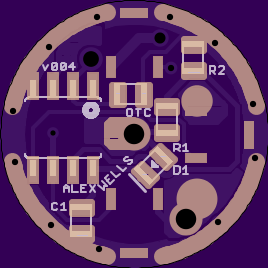
I’m confident that this can be done better, but here’s something:
17mm
similar design guidelines to the PZL driver
using smaller, rounded 0805 pads
centered via for BAT+ allows spring bypass on tiny spring
8+1 design w/ separate outputs on top
Ugly inside and out. Frankly the layout on the top side is pretty questionable.
I think I left a lot on the table in terms of making a clean, sensible layout. Maybe I’ll take another crack at it. Also, maybe I’ll create a driver thread for it… later.
I’m still getting the feeling that this could be done better, but I’ve created another layout for the top. This layout allows for a standard Dual-PWM config (8+1) or by cutting a single easily accessible trace it becomes a two-channel driver with 8x / 1x. [WIP] 17mm 9x 7135 for dual-PWM or white/red: A17-L81
So after finally thinking I’ve got my mind wrapped around the firmware, and going through two usbasp’s (first was apparently a dud), and then getting an SOIC clip with the MOSI wire clipped off by whoever put it up on ebay…
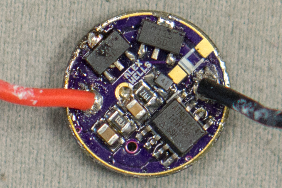
My driver is running quite stably… off of only one 7135 on all modes. I hate to be that guy asking a question without giving hardly any information as to what my set up is, but do y’all know of any glaring reason(s) why that might happen? Does moon mode need to be commented out so the MCU won’t be hunting for a grounded star that would enable/disable moon mode? Running the latest star_offtime, dual_PWM uncommented, dual_PWM_start uncommented and left at 8, turbo rampdown basically stock, high is commented out still. After looking at the firmware over and over, I’m relatively convinced it isn’t the problem as I didn’t change much besides uncommenting the obvious dual_PWM related stuff.
So I reckon there must be a short somewhere. But I’ve got no idea where. Would getting C1 and the OTC mixed up do that? They’re pretty darn similar in size and I can’t hardly tell which is 10uF and which is 1uF. I think I’ve got D1 oriented correctly… but just in case, if it were backwards would it cause the driver to run on one 7135 instead of all of them on turbo?
Kindof at a loss. The driver looks fine to me - no blobs of solder anywhere bridging components or anything like that. Almost seems like I don’t have enough on some 7135s maybe, but I built the driver with solder paste + hot air as I’ve done several times before successfully (with other drivers using attiny’s flashed by RMM, not by me). Any help greatly appreciated.
Might not be the caps making it do that, but they ARE backwards. And it does look like the diode might not be making contact on the MCU side. They tend to want to wiggle around when the solder melts if you have a little too much solder, and it’s really easy to get a little too much with that tiny thing!
Your 1912 should be a 223 according to the way Wight designed it. I’ve been using the 223 and they work beautifully. Have to change ADC_LOW to 124 and ADC_CRIT to 112 for a 3V warning and 2.8V shut down in the Low Voltage Protection.
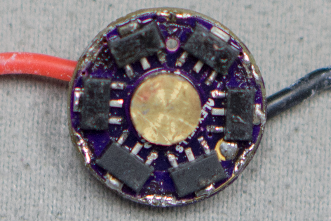
It also looks like the 7135 above Alex’s name is blown.
DBCstm, if those are backwards so are the ones pictured in the OP? I actually haven’t run that driver, so maybe they are…
That said, I wouldn’t expect the driver to function at all with a 1uF decoupling cap. Likewise if the diode was not making good contact, I’d expect no operation, not 0.38A operation.
I’d say that it’s time to get the DMM out. Get this driver wired up on the bench turn it on and switch to “high” mode and we’ll do some checking.
Check for voltage on the Vdd pin of each 7135.
Check for voltage on Pin 5 and Pin 6 of the MCU.
Take Vbat (solder on an extra little wire and hand-hold this) and directly apply it to the non-functioning 7135’s Vdd pins.
The Vdd pins are the ones wired back to the MCU’s PWM outputs (Pin5/6). Refer to this datasheet’s first page if you have any confusion, the pin is clearly marked: http://lib.chipdip.ru/709/DOC000709557.pdf
I lay out my components and leave the C1 cap in the tape. I put the OTC on the board before C1, then open the tape and put that one on the board. I always leave that 10uF in the tape til all other components are populated. Then it’s not a matter of me identifying 2 caps that are close in size, it’s ID’d by being in the tape, cut off the string of 100 from the package and identified one at a time as each component was laid out.
Incorrect. I just double checked. My 10uF caps are physically smaller than my 1uF caps. I also went over here and looked at bdiddle’s caps (#46). Bdiddle’s C1 is also physically smaller than OTC.