Nanjg-105c replacement w/ added functionality. [Regular firmwares can be used by bridging pins 5&6 to make it work like a 105c or Qlite - new functionality requires flashing a current version of STAR or similar.]
Features:
- 1mm ‘tall’ component keepout around edge. While all plastic packages are 1mm+ away from the edge, 7135 tab is actually only 0.5mm away from the edge.
- 7+1*7135 (so 8x) with dual-PWM, similar to RMM’s Moonlight Special (#1447) == identical functions, intended for use with the same firmware. Intended to achieve more efficient, consistent, and lower moonlight modes.
- Zener ready. [SOD-123, our standard sized Zener]
- Offtime ready.
- Covered (scrapeable) PB4 (Pin3) input/output pad. Use for temp sensor or FET turbo w/ a stacked FET. The pad is ~1x2mm in size.
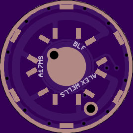
- A significant arbitrary aesthetic design goal should be obvious… hint: it involves a lot of 0805s in a straight line!
- Based on Cereal_killer’s post #44 in the DD+7135 thread I’ve used a larger GND ring on top where possible. The bottom remains 1mm. The exposed copper is 0.5mm on top and 0.25mm on the bottom with large ~1mm scallops.
- Like some other recent drivers, this driver does have a reverse-polarity protection diode but bypasses the diode for the voltage divider. Due to this we are able to use any diode desired. Ideally we use a protection diode with as low a Vf as is reasonable.
- The exposed spring pad is exactly 5mm, ignoring the via. The total copper under the spring is 6.4mm. [A signal trace is immediately outside this 6.4mm area, but everything should remain fully covered in resist out to approximately 7.4mm]
- Both power vias are 1.3mm.
- LED+/- pads are 2.6mm in diameter.
I established a very arbitrary design goal and stuck to my guns. All the 0805 components are perfectly lined up and spaced evenly from one another. Any differences in spacing are due to the low resolution render. Actual pads are significantly farther apart than they look. As far as the electrical design / schematic, this was directly inspired by the Moonlight Special driver. I’ve been discussing sequences of 7135s for a long time (and others were no doubt discussing it before I did). Under that system I’d normally put PWM on a single 7135 and then use toggles to turn on and off all the others in sets, typically organized something like (1, 1, 2, 4) or (1, 2, 3, 6) which allows the use of 1, 2, 3, 4, 5, 6, 7, or 8 IC’s at once (or 1 through 12 in the second set). At some point I came up with a hybrid driver which used an FET and all the other available outputs on an ATtiny13A in order to get as close to that ideal as possible + have FET turbo, but there are some downsides to that and more work to be done. Until RMM brought out the Moonlight Special driver it never occurred to me that there was any point to going less than “whole hog” on that concept. What RMM realized was that a single 7135 could maintain a very low, efficient, and reliable ‘low’ or ‘moonlight’ mode on one PWM output, and that if we hooked an additional PWM output up to another thing we could have both high and low current with PWM. (This driver is intended to use with either “full on” on all eight 7135s, PWM on all of the 7135s for all the regular modes, full on on a single 7135, or PWM on a single 7135 for the lowest mode.)
This driver has been cryptically named A17PZL, which can either stand for PWM, Zener, Linear… or PuzZLe.
![]()
While the power vias are suitable for soldering your LED hookup wires into at a very large 1.3mm, there are also giant 2.6mm pads which are directly across from each other near the edges of the PCB. For many installs these probably make the most sense.