It was not very expensive and I could order another flashlight and have it in 3 week’s time.
I do not like dumping things if they can be repaired or have parts replaced.
If you know where I can get this same driver let me know (contacted supplier & others on Ali and they cannot supply me. Also did image searches but nothing came up).
Also, if you have some idea how to repair the driver, let me know.
Basically, this is how it came to malfunction. Read next post please.
https://forum.allaboutcircuits.com/attachments/20250207_001646-copy-jpg.342205/
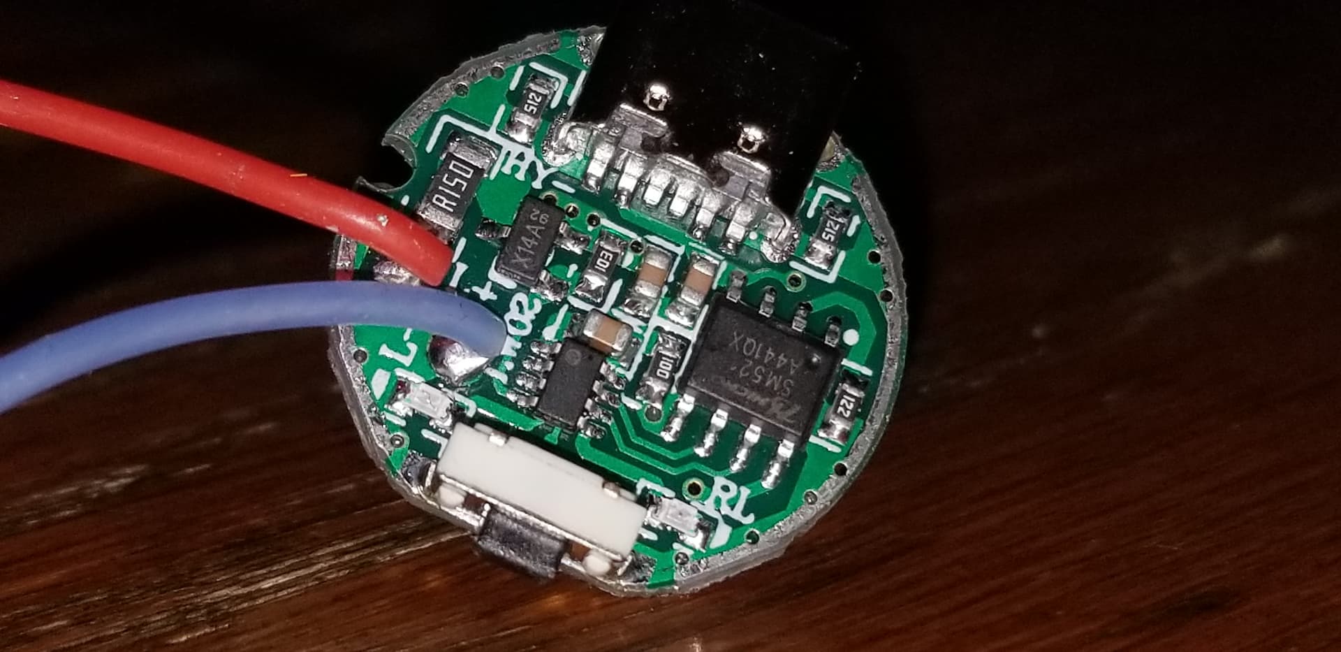
8. Voltage was showing, but no current flowed to output. R150 seemed to have been damaged from above actions.
9. Jumping the R150 worked OK though. So the R150 was removed and replaced by a wire.
10. Output worked fine but the on/off button lost functionality. It was ON all the time.
11. I had an extra switch at the motor so I turned it off for the night. 12 hours later when I tried again it would not turn on. I thought it was the battery drained, but it was not. Voltage was showing, but no current flowed to output (same as #8).
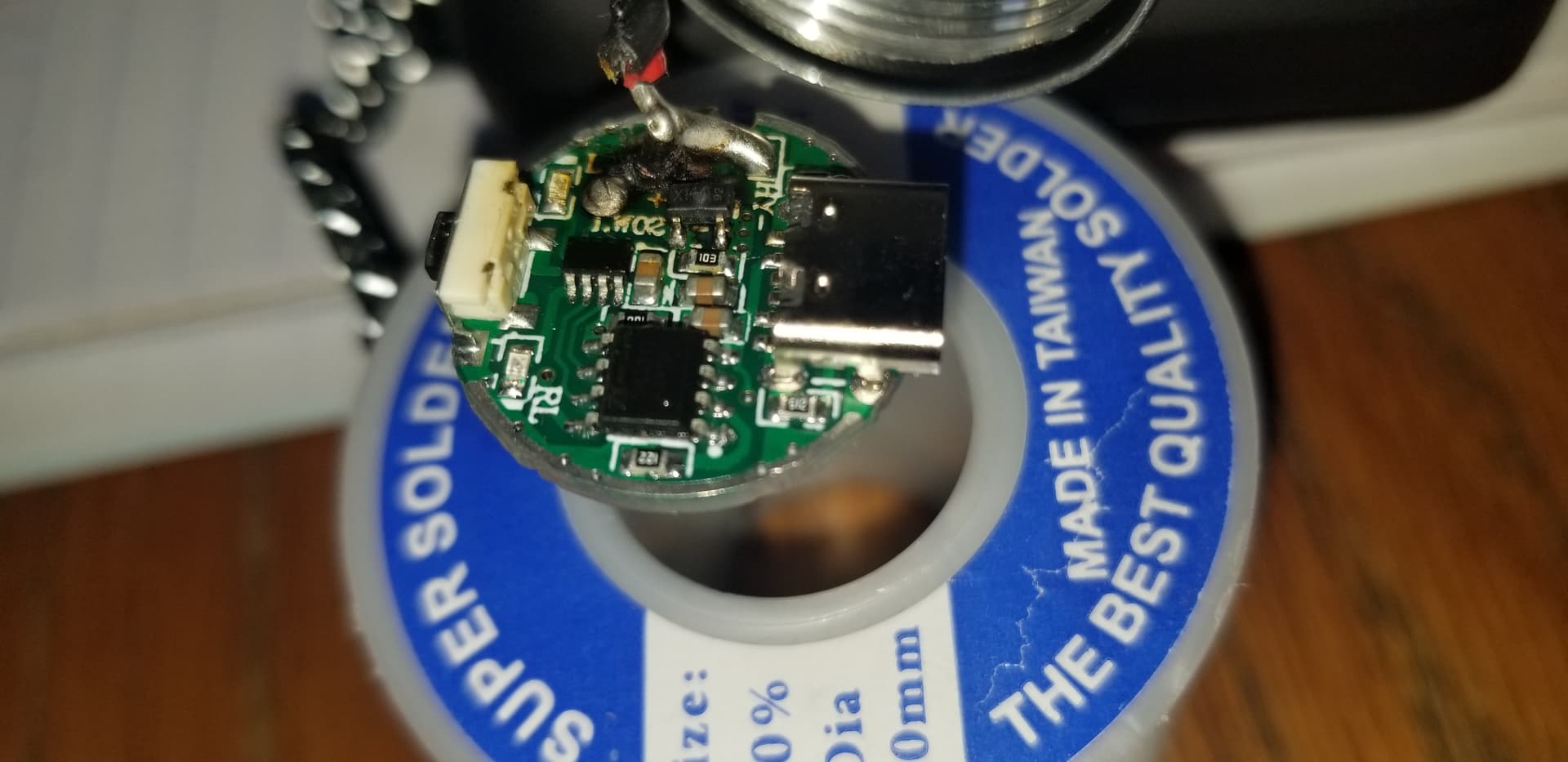
I also see scorch marks around the FET and darkening of the surrounding area probably due to overheating.
Looks like the FET must be replaced and with it the R150 resistor which seems to be vital for the proper function of the driver. I found this component A19T AO3401 SOT23 which seems to the equivalent to the X14A/92. I also found this component to replace the R150.
I am not an electrical engineer… Should I check anything else?
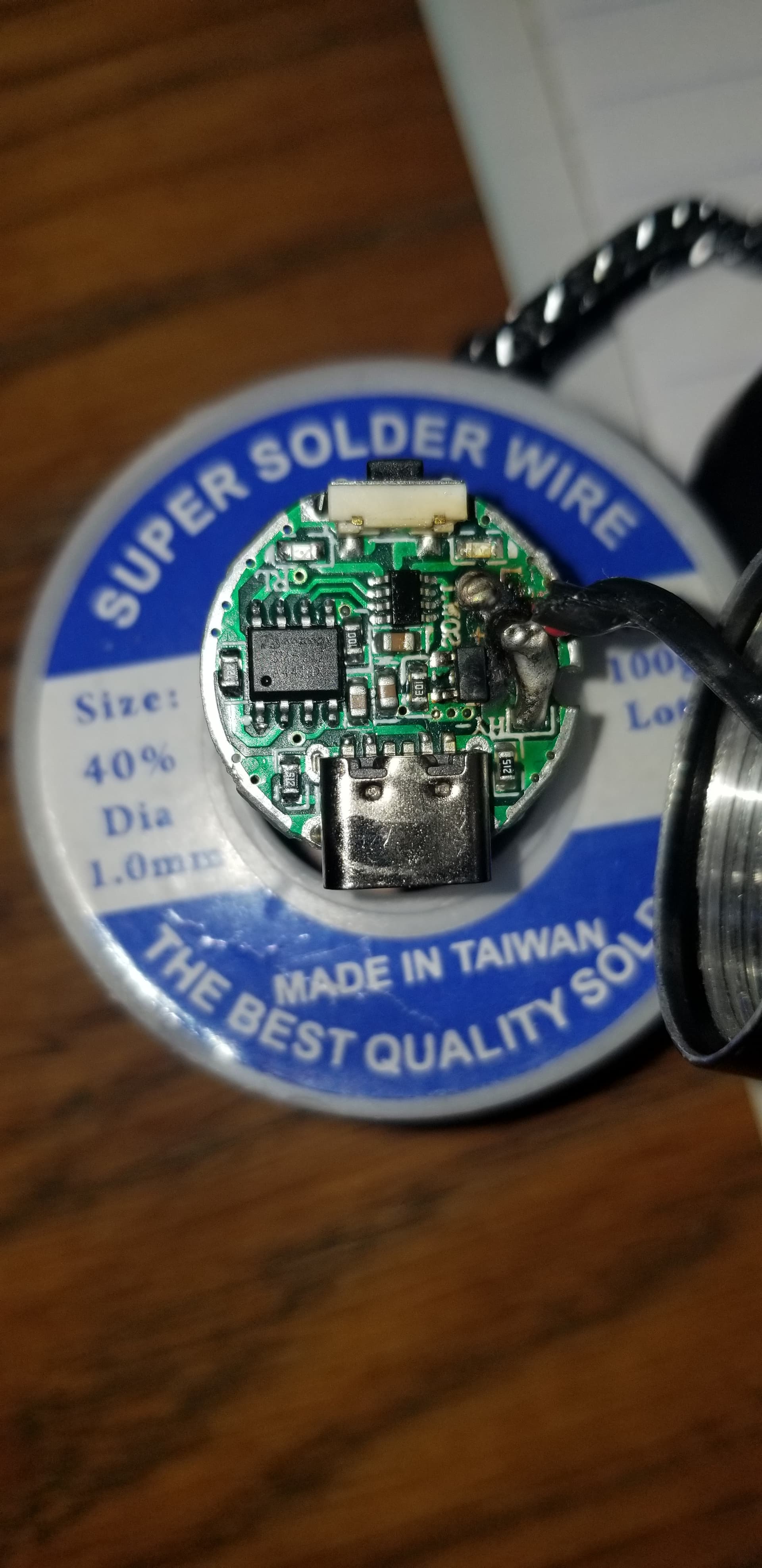
It is simplest and cheapest circuit to drive led. MCU (biggest chip) turning on and off that burned mosfet and mosfet output goes thru that R150 limiting resistor. If MCU still alive it should work again. Check some caps on output if they are not shorted too. That smaller 8 legs chip probably linear batt. charger.
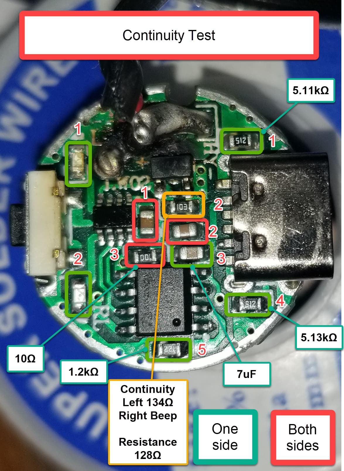
Looks like capacitors 1 & 2 need replacing right? what values though???
Also resistors 2 I guess?
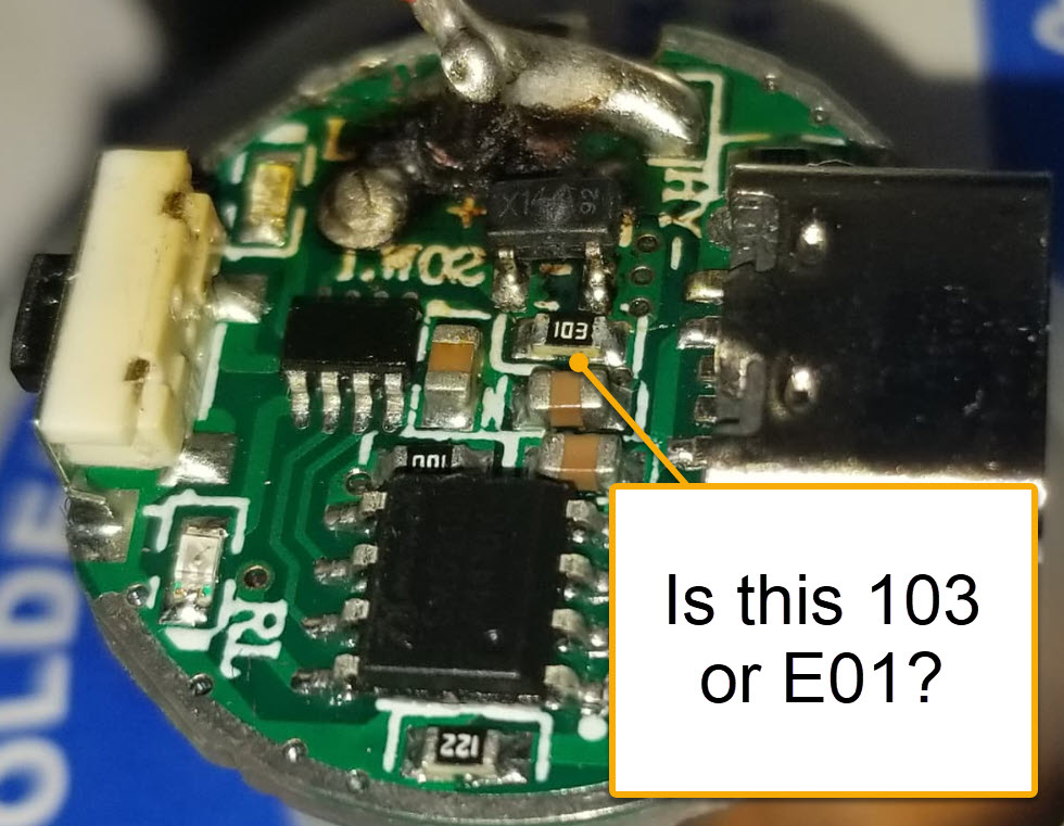
Resistor 3 has correct value 10 Ohm but shows continuity from both sides… because of low resistance probably?
Is there any other test I should do e.g on the larger chips?
I ordered a new flashlight. When it arrives, I will test the capacitance of the broken capacitors and order new ones. Do I still have to unsolder the good capacitors to measure them?
Why are you centered on the capacitors when you have a chip that is visibly broken?
Measuring something in circuit is not a good idea because the capacitors could be perfectly working and the continuity could be through said dead chip or something else.
Not centered on capacitors. I have ordered a replacement chip already and resistor as mentioned above. I turned my attention onto the capacitors so as not to waste time and place a timely order if possible since it will take 3 weeks for the parts to arrive.