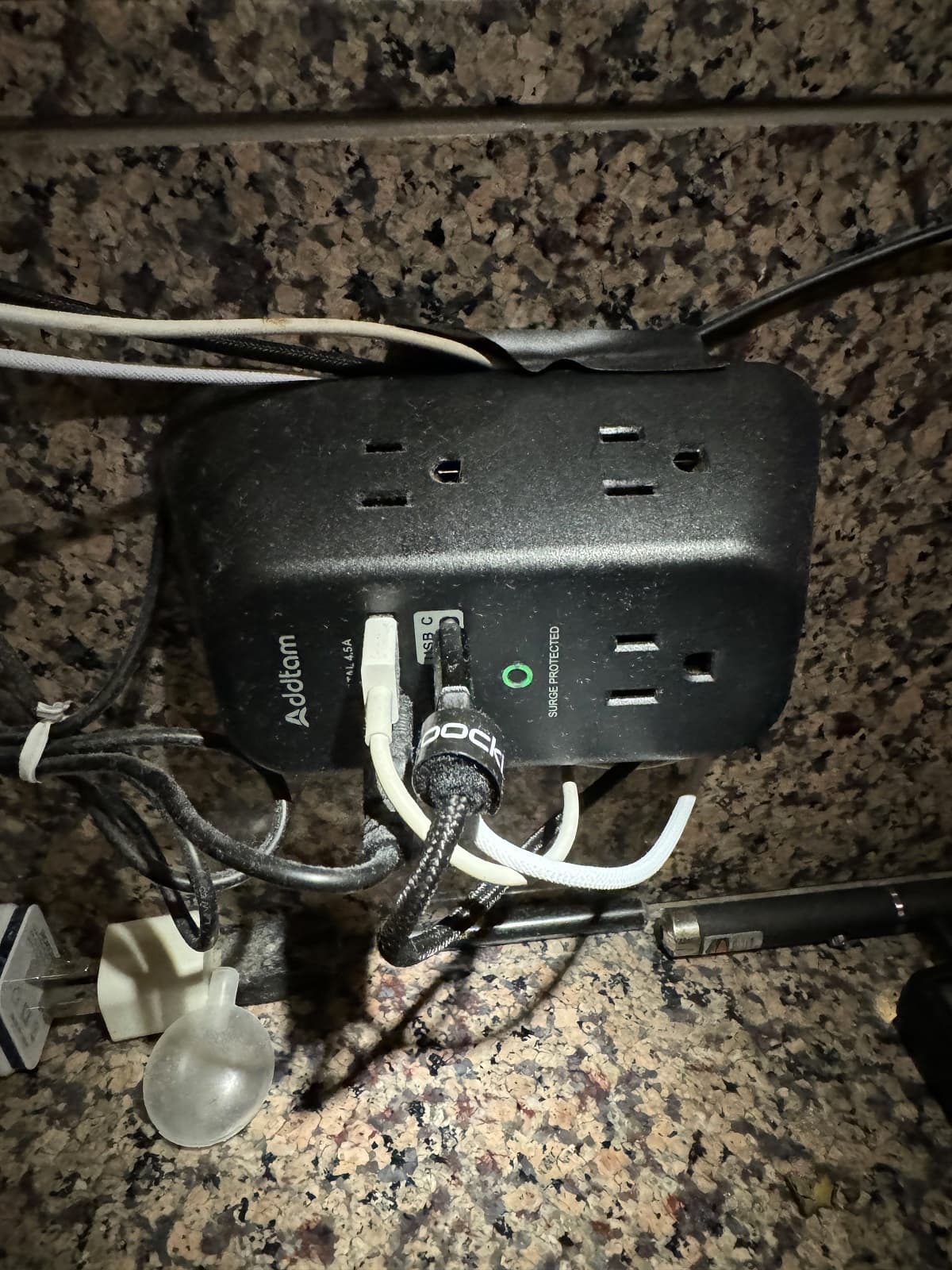
Hopefully the word will get out about the USB over-charging for those that bought these. A 60amp cell cooking off inside the tube is not going to be good.
No word from Nealsgadget and probably won’t be but this could be a dangerous situation as I saw continual slow charging past 4.7 volts…
Yes that is the biggest problem. I can avoid using the USB charging, especially since I know of the issue. Not everyone with this light will have that benefit.
Agreed. Same here. The minus point of this light is that dangerous built-in USB over-charging. The pluses are best Nigthwatch side-switch to date (tactile feel and travel), tremendous brightness for the size, and this tiny size makes it among my most favorite of all my flashlights. To witness this tiny thing lights up the side of a hill is an unforgettable experience.
So glad my LED didn’t get damaged. Just two AM04 batteries killed . Re-testing with properly-charged (lower voltage 4.2 instead of 4.6v) shows the single remaining AM04 leading the way with 15,000 lm.
Just trying mine again, it terminated under 4.20V during the review, but I usually unplug the cable as soon and the red light goes blue or green, etc, as I’m always reviewing non-stop and out of 500-600 lights the highest over-charge I’ve ever seen was 4.24V, if I remember correctly, so I just tend not to leave cables plugged in. I’ll try this light again with different cells.
*Update, the blue light came on at 4.16V and my 100W capable charging Type-C to C wire shows 0W charging off a 100W GAN charger. (SAMSUNG 40T). I’ve left the USB in for 80 mins, the switch light stayed blue, and the voltage hasn’t budged from 4.16V. I’ll try charge it off a lower wattage power bank.
Update, a MOLICEL P50B got the charging complete blue light on at 4.18V, I left it 30 mins and still 4.18V. 3 hours trying now on different wires and chargers and nothing out of the ordinary.
Good to see that the problem does not effect all of the lights. Though I am not sure I want to sacrifice a perfectly good cell to see whether mine has the bug.
Honestly though, I have lots of cells and several good chargers. I typically just swap in a charged cell and put the one needing charging into the MC3000 or S8000 to top it off. I have never been a big fan of onboard USB chargers anyway.
But that is a topic for a different discussion.
Thank you. Glad to hear that there is some hope of a work around.
I used a Quick Charge power supply, is it possible the over-charging is due to an adverse interaction between the A54U and the Quick Charge “algorithm,” if there is such a thing? @Lips what did you use for the power supply?
Well , I just had to know. I took a Samsung 50E that I had from some pack pulls. It was about 4.10 volts to start ( a cell I wouldn’t mind frying) . I plugged it in to a 100 watt (pretty much every charging protocol supported) power supply through a USB power meter. I charged it until the light went blue. Checked the cell voltage at 4.22. Stuck the cell back in until the light turned blue again and watched it. The USB meter went from 3.2 down to 2.8 amps and stayed there. I waited a few minutes, pulled the cell and checked voltage. It was at 4.35 volts. So the internal charger on the light is not cutting off when it should.
Checking with other generic, non Quick Charge, power supplies and again confirming the charging system continues charging after battery is full. @Sirstinky also has a review sample, wonder if you could pls check yours?
I did not have any issues with over charging on my sample (or the LW55, which I think has a similar driver). However, I didn’t test any other batteries besides the included one.
I have seen 4.25V with an AM04, using an Anker 65w QC supply. Remember thinking that this is a bit high for comfort. However, I pulled the cell pretty much right after the charging indicator switched to blue. Will now test what happens when I keep it plugged, with an old Samsung cell.
Then charged with the on-board USB using this. This slow charger brought the cell up to over 4.7v (I was unaware of the voltage). I noticed red to blue change on the switch but left the light on the USB for a little while.
.
.
.
.
Used the light and noticed a flicker when I went to turbo. I didn’t see the burnt LED at this time. Pulled the battery and checked voltage with a Nightcore charger and got no reading. Puzzled I tried the Vapcell charger and got no reading. Got a multi-meter and saw 4.65v. Puzzled by this I looked the light over and saw the burnt LED!
.
.
.
.
.
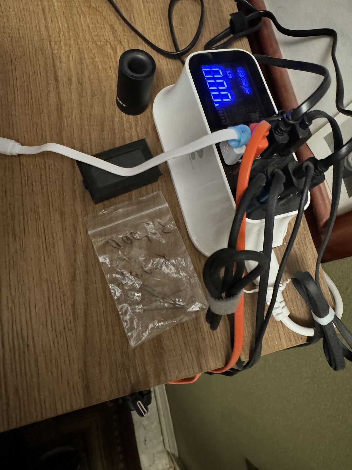
I then put the cell back in the light and tested the USB charging on this display charger to see if power was going into the cell even at 4.65v. It began charging at 1.07 amps. Let it run a minute and ended the test; put the cell out in the garage inside a large metal container for safety…
So, I tested this myself with my A54U, trying to replicate the findings of @Lips / @cannga / @Mandrake50. The battery is a Samsung 40T, which I no longer use. I connected an USB tester (HiDance HDC-085C) between the cable and the lamp. The power supply is an ordinary, “stupid” no-name 5V/3A USB-A to USB-C power supply (no QC/PD).
1st round
Battery has 3.72V before charging
Charging starts with 13.2 watts (4.7V and 2.8A on the USB side), the charging LED lights up red.
Charging is terminated, the charging LED switches to blue. The USB tester shows 0.00A charging current.
The battery is removed immediately. Cell voltage is 4.18V (so far, so good).
2nd round
The battery has 3.8V. Same test as the first, but I leave the charging cable connected after termination (blue LED). The USB tester shows a constant 0.00A charging current after termination.
After about an hour, I remove the battery. Cell voltage is 4.19V - all OK.
3rd round
This time I plug the USB connector back into the lamp without discharging the battery first (starting cell voltage is 4.19V). The LED switches to red, the lamp charges for about 1 minute with approx. 8.4 watts (USB side), then it terminates again (blue LED). The cell voltage is now 4.23V. Not ideal, but also not dramatic or dangerous.
I plug the USB connector back into the lamp. This time, charging (at 8.4 watts) only takes about 10 seconds until termination (blue LED). The cell voltage now shows 4.24V
Disconnect and reconnect again. Termination after about 4 seconds (blue LED). Cell voltage reads 4.25V
All further attempts terminate after 1-2 seconds. I did not manage to get the cell voltage above 4.25V.
4th round
This time I start with a battery voltage of 4.08V.
Charging with approx. 8.4 watts, termination after a few minutes. The battery has a voltage of 4.23V - a little too high but still within spec.
Observations/questions
I have not (yet) been able to reproduce the massive overcharging described by others. So far, this would rather indicate that there are some faulty units in circulation.
That said, the charging circuit certainly seems to operate quite coarsely and unorthodox . In particular, my unit’s charging current never drops below approx. 1.8A on the USB side, i.e. approx. 2.0A on the battery side (minus the losses of the charging circuit). That seems very high to me.
Shouldn’t a proper CC/CV circuit decrease the current during the CV phase and then terminate at about 1/10 of the current (i.e. 300-400mA in this case)?
@Mooch, what is your view on this, is this bad for the cells?
In the next step I will test the whole thing again using a more up to date Anker 100W QC/PD power supply.
UPDATE: I have now completed a second run of tests with the 100W QC/PD power supply. It showed the same characteristics and results, with the exception of slightly higher charging currents (17W initially, 10W right before termination, both USB-side). Still, I cannot get the cell over 4.25V.
Can I ask when you got your A54U? I ask because we have three people that got them quite recently that are seeing the charging issue. Two reviewers that got them (probably) much earlier that don’t see the problem. Just wondering if it may have been a problem with lights produced later in the production run ??
Not bad for the cells but can result in a less-than-complete charge because there’s no CV-stage “topping off” of the cell’s charge.
To keep the charge circuit in CC mode they’d have to set a high charge voltage and then use a cutoff circuit to stop the charge early, as soon as the cell reached 4.20V or so.
I’m wondering…with no evidence to support this yet…whether this was done to speed up charging? Use a high charge voltage, skip the topping off, and claim fast charging.
But maybe some of the lights don’t turn off charging when they should and end up going up to the actual charge voltage they use? All conjecture for now but it fits.
That’s an interesting idea, and would make sense (both explaining the idiosyncrasy of the charging circuit, the motive for it, as well as the possible failure path).
@Mooch - any idea how to further substantiate this? Would it help for me to disassemble my unit and make photos of the circuitry?
Circuit analysis and actual testing would be the standard, and best, way to confirm what design decisions they made and to try to figure out what’s going wrong.
You can try taking photos of the top and bottom of the pcb but they would have to be verrrrrry good shots to even being to have chance of possibly tracing out the circuit and looking up part numbers. I just wouldn’t have the time to do that though.
I’ve tried to get a look at the driver, but this requires unsoldering as the PCB does not move much after removing the lock ring. At this stage, I am not prepared to do this, as I suck at soldering.
Question: is it possible to track charging voltage while charging the battery?
I tried to do this, removing the tail cap and connecting the probes of my multimeter to the tube and the negative side of the cell (while charging), but it shows approx. 2 Volts?
Apologies if this is a stupid question
Yea, sounds like too much trouble. Thanks for trying though!
Always possible to track charging voltage but it can be pretty inconvenient sometimes (drilling, soldering on new wires, etc). I don’t know where you can access both ends of the cell (electrically) in your light so I don’t have any good recommendations.
You can measure your cell voltage while it’s outside the light so you know when you’ve found the correct voltage when reading from various parts of the light (after the cell is put back in).
What a puzzle this has been. What with some lights affected and some not. I’ve finished my testing with several power supplies and batteries - all over-charged.
 . Re-testing with properly-charged (lower voltage 4.2 instead of 4.6v) shows the single remaining AM04 leading the way with 15,000 lm.