Review: UltraFire T90 SST-90 3x26650 Flashlight
Relic's Rating: ★★★★☆

Wallbuys recently added this light to their inventory and after some debate I decided to order it. Wallbuys shipped it the next day and it arrived at my mailbox 11 days later.
The package included the light and three 18650 adapters. The strap and accessory bag was missing.
Update: I contacted Wallbuys via PM regarding the missing items and Cherry replied within an hour informing me that the missing item was retrieved from the supplier and will be shipped before they break for holidays (I just checked and it has shipped with tracking number). I'll add my review of the strap and bag when it arrives.
The exterior packaging was good, a cardboard box covered in bubble wrap and completely sealed with tape. However, inside was an unfortunately familiar story. The main body and head were in a bubble bag next to the extension tube. The flimsy bubble bag tore and the parts were banging into each other. the result is a few knicks and scratches in the ano. My Tr-3T6 from DX was in a similar package. I believe this is how they come from the manufacturer, and the sellers do not open the box to repack the items. This would be a good idea, Wallbuys and any other sellers listening. Before you ship a light, open the box and wrap the parts in another layer so they cannot get into each other. It might save you from a few returns. I will not return mine based on some scratches, but others might.
OK, on to the review.
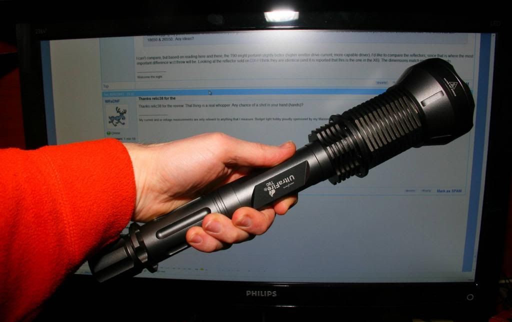
My first impression when I opened the box; this thing is huge! I mean huge! Let's compare to a familiar light, the HD2010:

The HD2010 barely reaches up to the T90 body! And from the front:
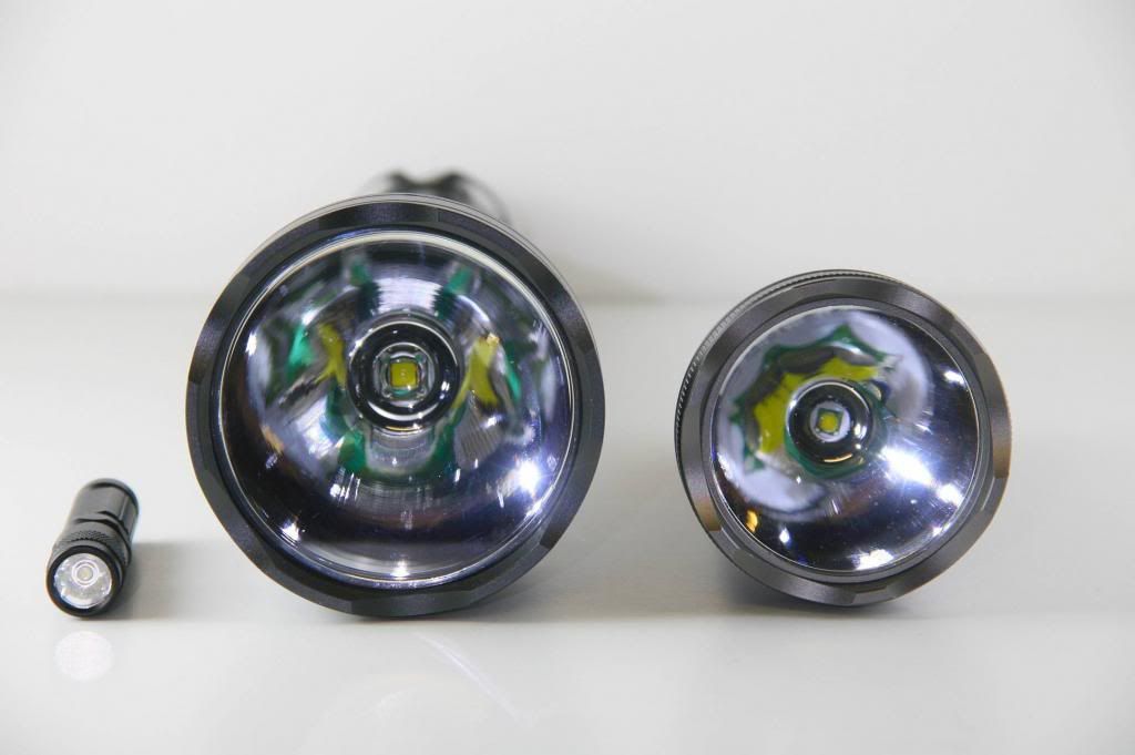
(OK, I put the Tank007 E09 in there for fun)
There's a significant jump in reflector size over the HD2010.
On the other end is a monster of a tailcap. Even with the length and being top-heavy, this light will tailstand on a flat surface:
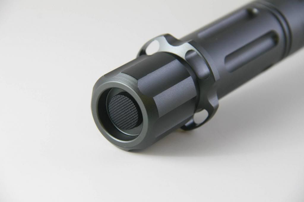
Compared to an SK68:

Completely useless fact: The T90 tailcap weighs the same as an SK68; just to add a little more perspective. :)
Overall, the machining is very good and the ano is decent. There are a few scratches from shipping, and I would expect a few more from normal use. It does not feel like HA-III grade ano. The threads are OK, trapezoidal and fairly smooth. The tailcap threads are good, well lubed and feature double O-rings. Other threads were dry but smooth once lubed. There are dual O-rings on the main body tube, however this light does not support a two cell configuration. O-rings are in place at each joint, however two locations are inadequate meaning the light is splash-proof only as shipped.
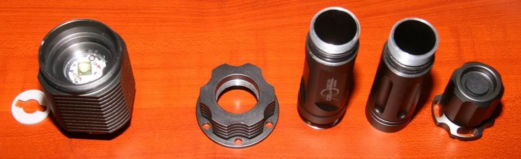
Moving on to the tear down:

The head is so big it breaks down into three pieces (the reflector cone is removable too). An unprotected 26650 is shown on the right.
Update: Feb. 8 2013: I just received my TF Flame Protected 26650 cells from Fasttech and can confirm that they will not fit. not even close. I cannot even get the tailcap to the first O-ring. With one TF protected and two TF unprotected I can just get it to close over the last Oring, but I didn't want to try going for completely closed. It may be possible by modding the driver cover so the center portion is removed allowing the battery to directly contact the driver spring. That may be just enough space to allow these cells in. For reference, the protected cells are 68.5mm long and the unprotected cells are 66.6mm long.
Tearing the head down further (I got lazy on my shots from yesterday, no light box):

And the rest:
The head is a one piece with integrated pill. This makes emitter access a pain, but I think it's a good thermal design decision. That's a 40W emitter; there's a lot of heat to deal with. Based on the ample heat sinking, it should come as no surprise that heat is very well managed here.
Looking closer in the emitter end of the head reveals the first issue; workmanship in this area is not the best.

I'm not sure what the heck happened here. Whoever put this one together either had some bad luck or really needed to go. There are two things wrong here.
First, the screw on the right stuck up too much, so what to do; get out the die grinder and shave the head down. OK. Must have run out of low profile screws that day.
The second problem; the LED was not reflowed on the center of the star. Of course, the star is perfectly centered in the head, so the end result is an out-of-center emitter. To make matters worse, that's Fujik under the emitter. I suspected this when looking at the initial beam pattern.
Ultimately I did reposition the star so the emitter was centered (see mod in first reply for details). After this, the beam looked a lot better.
here is the front after centering (sorry, no before shot):

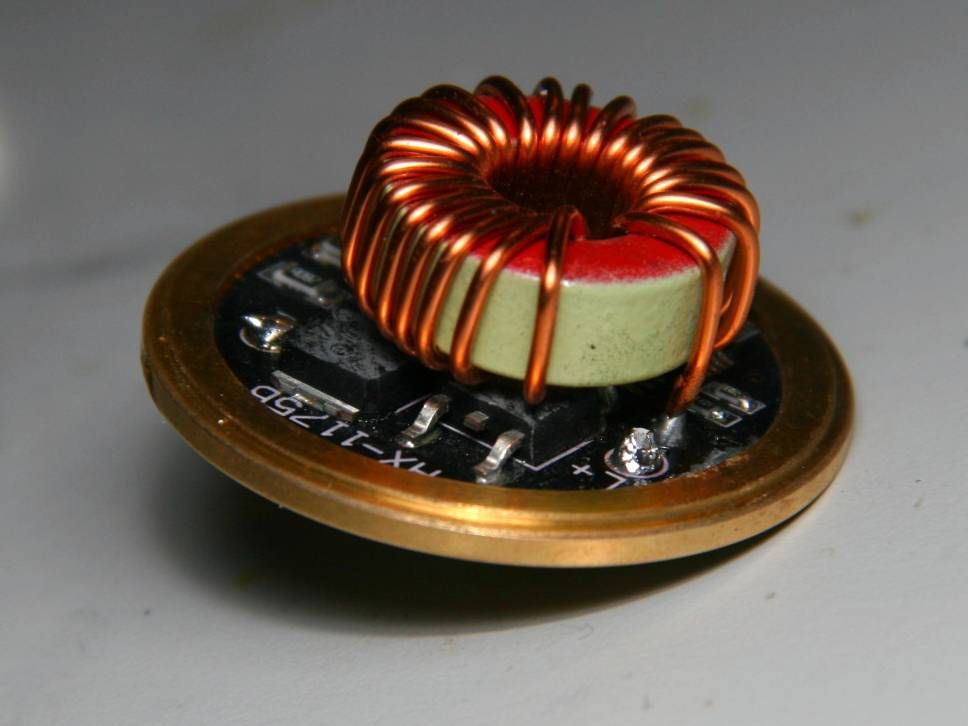
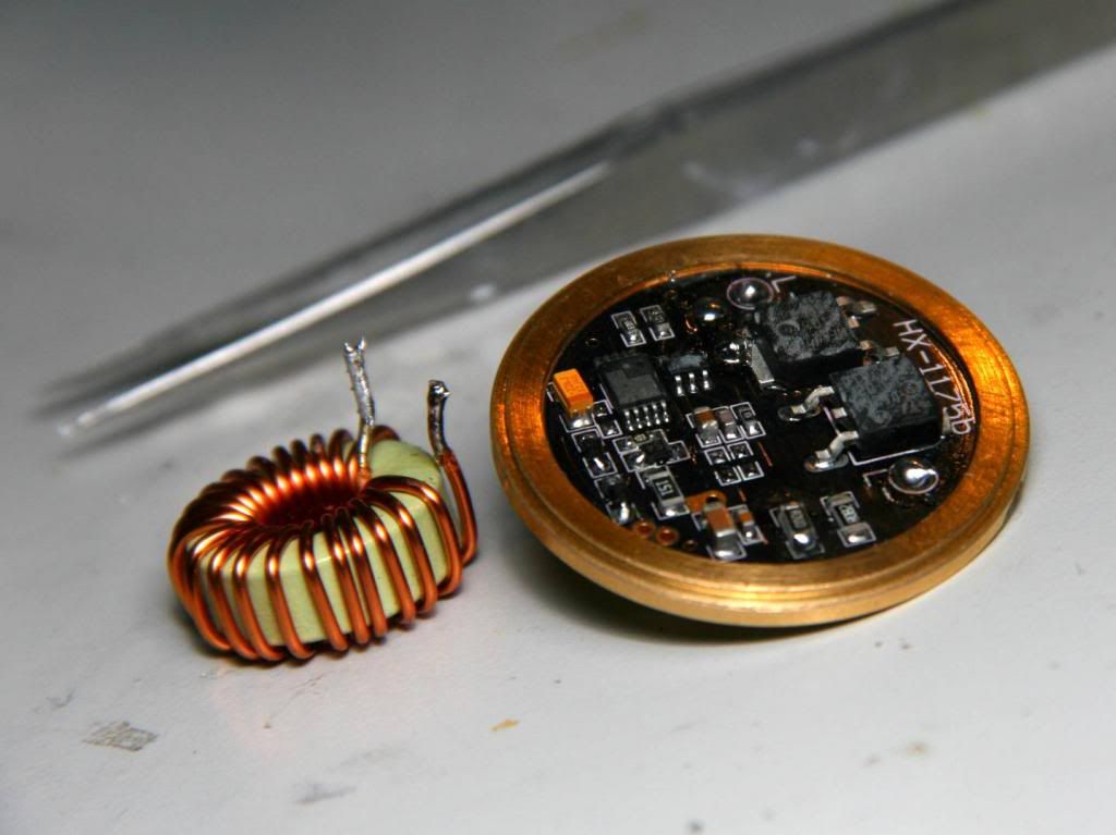
OK, so at this point, I'm starting to get worried about what is on the other end of the head; the driver. let's take a look:

The driver is press fit into place with a brass ring and plastic cover (not shown, see below). This made it difficult to remove. With some prying and poking it popped out.
My first reaction was, "That's it? This is supposed to drive an SST-90?". My TR-3T6 has a way larger driver. Based on my testing, physical size isn't everything; this is a very good driver.
At stock it pumps seven Amps into the SST-90. This is the highest I've seen. Most reports of the TF X6 driver are around five Amps at stock.
Efficiency was very good too at 86%. My spirits lifted after these test results; there is hope for a resistor mod (Check the first reply, you will not be disappointed).
before I forget, here is the driver cover, Battery side then driver side:


The driver has a rather small spring that contacts the center piece in the cover. I added some copper braid to deal with the relatively high battery current (especially after mods). The tailcap was also improved dramatically with a little copper braid. At stock, I got 260mV at 3A. After the braid, it dropped to 64mV at 3A. The switch itself seems to be very good.
I used three unprotected 26650 cells in this light. I do not have enough protected cells to determine if they will work. It seems a bit loose with unprotected, so there may be hope. I may add a nice short strong spring to the driver cover to reinforce the cell contact.
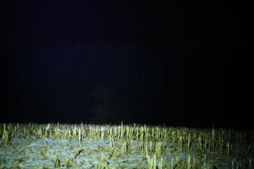
Indoor Beamshots:
Here are some beam shots on a white'ish wall from 1m away. Camera settings were f/8, 1/30s, ISO 200. The black dots are 16" apart horizontally, 12" apart vertically. The spill is good for this kind of light; low enough to not distract, bright enough for close-up visibility. This reflector is quite smooth (one minor imperfection not affecting the beam) and there are no visible rings. With an emitter this size, there is a large four-petal flower for a hotspot. The hotspot is quite large (maybe slightly larger than the HD2010 spot) which I find more useful than the tiny C8 XR-E spots.
High:

Medium:

Low:

There is noticeable PWM in Medium and Low. Medium is about 50%, while Low is about 10%.
Dimensions:
- Overall Length: 354mm
- Bezel Diameter: 79.4mm
- Head Heat Sink Diameter: 62mm
- Neck Heat Sink Diameter: 54mm
- Body Diameter: 35.6mm
- Tailcap Ring Diameter: 46mm
- Tailcap Diameter: 37mm
- Reflector Inner Diameter: 67.5mm
- Reflector Outer Diameter: 73mm
- Reflector Depth: 51.8mm
- Reflector Emitter hole Diameter: 12.4mm
- Lens Diameter:73.5mm
- Lens Thickness: 2.45mm
Weights (without batteries):
- Overall: 768g
- Head: 498g
- Neck: 62g
- Body Tube: 76g
- Extension Tube: 65g
- Tailcap: 66g
Performance (stock, 12.6V supply):
- Light Output: ~1200 lumens
- Beam Intensity: ~50kcd
- Power In: 12.6V * 2.54A = 31.9W
- Power Out: 3.86V * 7.1A = 27.4W
- Driver Efficiency: 86%
Power Source Options: 3x26650 (recommended) or 3x16650, unprotected cells only. Protected cells are not likely to fit.
Switch type: tailcap, reverse-clicky
Modes: High, Medium, Low, Strobe, SOS
Mode Memory: Short-off mode memory (while on, quickly half-press the switch to move to the next mode)
Thermal Management:
Timed measurements were not taken before the mod (I just couldn't wait). On a 20 minute run at ambient of 19C with no air flow, the head quickly heated up to 38C and slowly continued to 42C before the test was stopped. Measurement of the emitter star immediately after turning off gave a temperature of 43C. Thermal management is very good; no surprise there. there's almost one pound of aluminum just in the head. Even with that, external temperature starts to rise within 15-20 seconds of turning on. Heat is conducted away from the emitter very well.
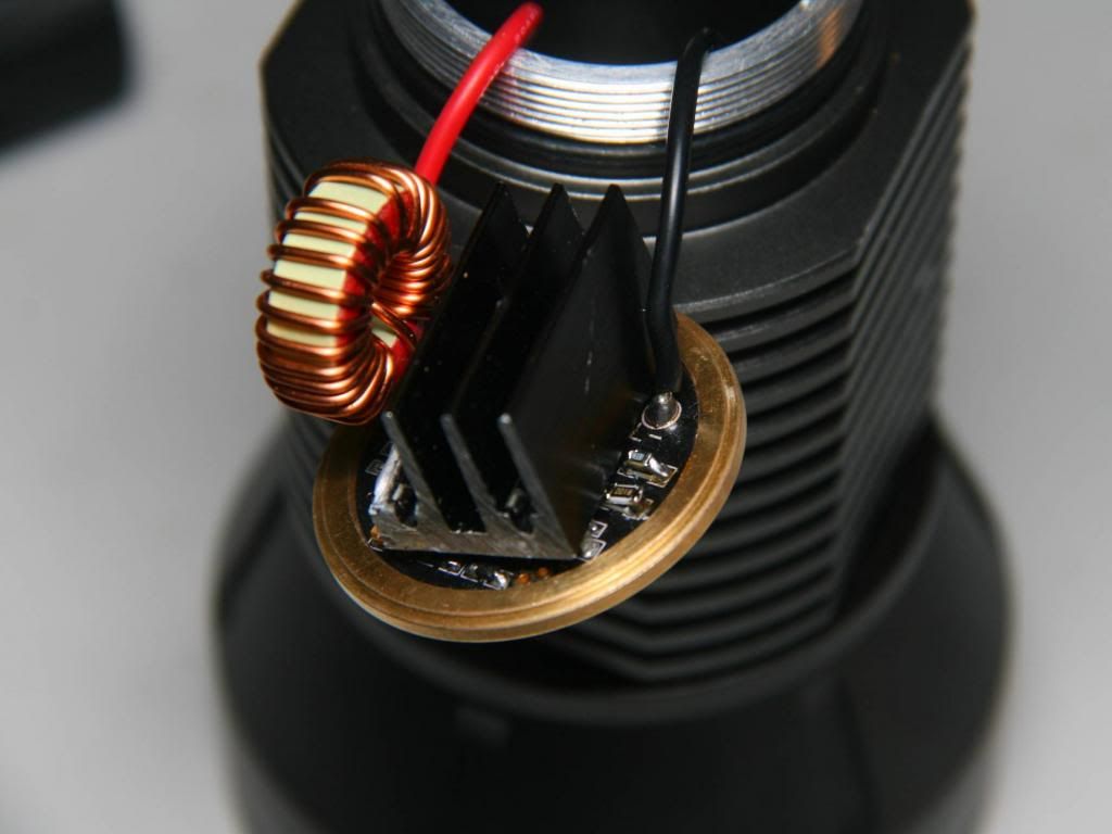
Driver thermal management is also very good. The large brass ring does a decent job of pulling heat away from the PCB. Still, the driver FET and diode get quite hot after a five minute run (FET measured at 95C, diode not far behind) in open air. Any resistor mod should be paired with a heat sink on these critical components (see my mod entry below).
Conclusions:
I like this light. I had some ups and downs when I first started looking at it (I like the look (and it's huge), poor workmanship in emitter area, excellent driver). After fixing the emitter alignment (hopefully I just got a bad one) I like the beam pattern. To be honest, I didn't get a remarkable increase in throw after alignment (It went from 46kcd to 50kcd), so a minor misalignment is more of an aesthetics thing.
Relic Recommended, especially for modders.
Thanks for reading! searchID8934