Modding, reverse engineering and bugfixing
After plenty people asked, I decided I would risk my light to try and disassemble and bugfix it. So, let’s deep dive into the guts of a HD10!
Disassembly
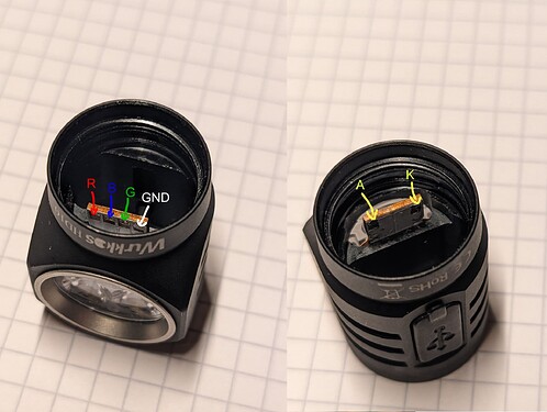
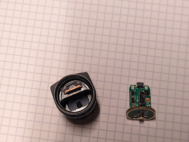
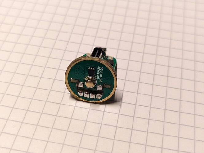
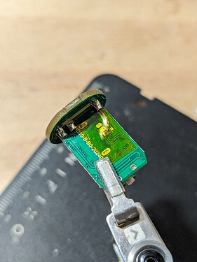
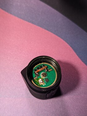
The light is surprisingly easy to take apart - When you unscrew it, you see a second vertical daughterboard protruding through the driver board. This is the MCPCB. It is held in place by 6 solder joints to the LEDs.
The MCPCB can sadly not be removed without removing the bezel, which is pressed into the body. So the LEDs and TIR can not be accessed without accepting damaged hardware. Unlike the driver - desoldering those 6 joints with the help of solder wick is easy, and then the driver can be slid out of the light.
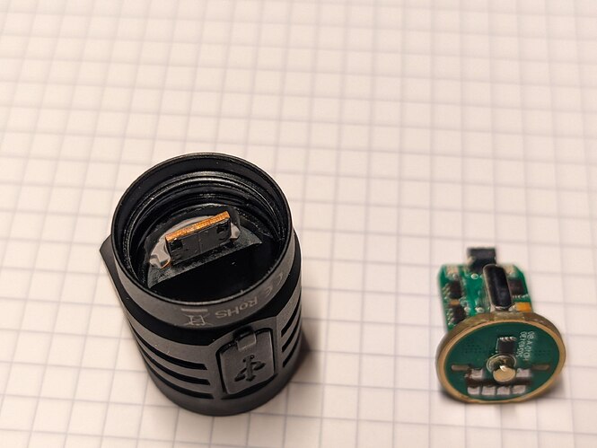
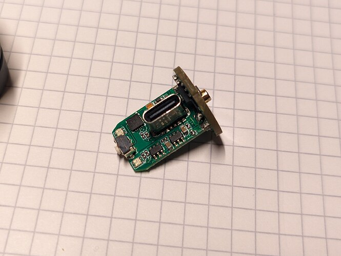
This is the result after removing the driver PCB. Most of the logic sits on the vertical daughterboard, while the actual power semiconductors are located on the PCB that directly interfaces with battery and LEDs - this is good design, and saves a lot of transition resistance. Overall, the driver is mechanically nicely built. I like it.
Reverse Engineering
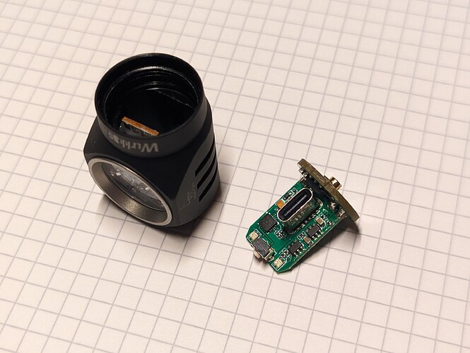
Now lets put the head and MCPCB aside and look at the driver itself in more detail.
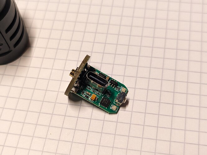
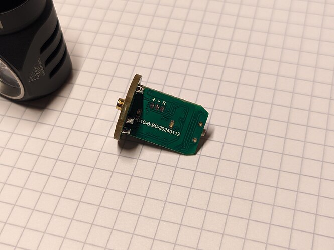
Now, what do we see here? An attiny1616? Yup! Flashing pads? Yup! In the worst possible spot, inaccessible inside the light -.-
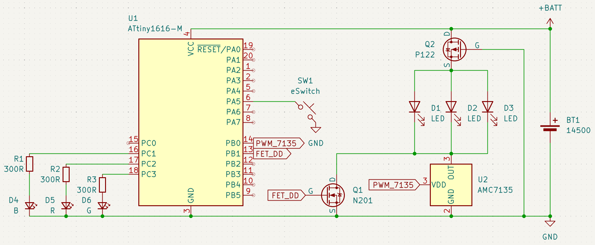
On the battery side of the driver PCB there is a 6-pin component marked “P122”, presumably a p-ch MOSFET for reverse polarity protection. On the other side of the PCB there is another 6-pin marked “N201” which is a n-ch MOSFET for the direct drive modes. Next to it we find a AMC7135 for the regulated modes. I traced the most important connections and drew up a simplified schematic. Keep in mind this is no complete schematic, and heavily simplified, to only show the basic connections. The fact that all 3 AUX LEDs have the same 300R resistor might explain the weird colors… Green should have a slightly higher value, red a significantly lower value for similar perceived brightness…
The pinout is exactly the same as used by many Wurkkos lights, among them the TS10 RGBAUX.
Another curiosity of this design: It uses TP4057 battery charging ICs, which are 500 mA fixed single cell chargers. For some reason, instead of using a single 1 A chip, they paralleled 2 500 mA chips. I have never seen this before, but apparently it works, so… Well. Curious, but not an issue ![]()
Fix #1: Hardware
At this point I was positive I could simply flash the TS10 RGB firmware directly from Toykeeper, but I wanted to keep the option of reflashing the light later on, so a redirection of the flashing pad was necessary. For this I used a thin piece of enameled wire I had at hand, and covered the solder joint in Kapton tape (as the exposed flashing pads are rubbing against the alu flashlight head… This has the potential to short out the light. No more, thanks to the Kapton! This wire was barely thin enough to fit through the cutout for the MCPCB. Not ideal, as it might eventually wear down from vibrations and short against the MCPCB, but works for a proof of concept. On the other side I stuck a piece of Kapton onto the PB, then a piece of copper tape onto the Kapton, and soldered the wire to it. This gives me a very rudimentary “flashing pad”. Might make a proper thin PCB exposing +, - and R some day, but for now… It works. Ain’t pretty though, I’ll admit that. It’s 2 AM now and I just wanted this thing working.
Fix #2: Firmware
In the review I spoke of erratic behavior, which I eventually pinpointed to a very weird issue: It appears that this light was configured as a dual channel light, with the second channel not having any LEDs connected, but still being present in firmware. This allows to get “stuck” in the second channel mode where the behavior of the light appears erratic and wrong - while in reality it is simply trying to turn on LEDs that do not exist, resulting in a confusing behavior (instead of toggling between on and off, aux leds on you toggle between light would be on, but no emitters are on, so effectively it is off and off, aux leds on. My best guess is, Wurkkos tried to recycle an older firmware of a dual channel light, added RGB aux to it, and flashed that.
Since the pinout (and presumably power/setup of modes) is identical to the TS10 RGB, I ended up simply flashing this firmware, directly from Toykeepers Github repository, in the latest version. And see there - no more bugs. My light behaves exactly as expected now. I will keep my eyes open if I can spot any more issues, but for now it seems to work perfectly.
I really wonder why Wurkkos went through the trouble of developing another firmware, instead of reusing the perfectly fine TS10 firmware? I do not know. @Wurkkos_Terry please do not ship the light with the firmware of the testing units. Use the TS10 AUXRGB Anduril 2 (or a firmware based on that but with changed brightness levels, if you prefer) instead. I think pretty much all issues people had with HD10 test samples (apart from the one by @wolfgirl42 where the electronics actually fried) were caused by this strange firmware, and the hardware is actually fine. I can ofc not guarantee that and will need further testing, but the main issues I ran into and could reproduce are now gone. The light is so much more fun to use now that everything works ![]()
