Here is a test of the second LED DavidEF kindly sent me
This one is a Shaved SST-90.
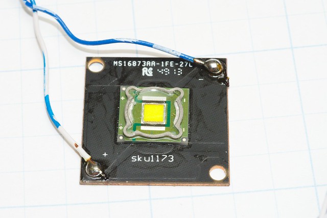
I managed to solder on some wires without messing this one up.
Just for fun I thought I’d get some voltage measurements.
The overhead lights in my office generated 0.4v. -
The Sofirn SP70 on High revved it up to 2.2v


The BLF – It’s a gateway drug….
We pause this testing to spend money on a PICO scope.
I blame Terry and the rest of BLF for this. I could have been buying lights instead.
But Nooo… I’ve got to see what’s going on with the lights.
The old BK scope is a pain to use and capture a picture.
The 192KHz sound card can’t get enough samples to look at shorter wavelengths.
This is how it starts – Come here looking for info about some light. Start reading and learning.
Discover some nifty lights that are too interesting to pass up. Makeup some excuse as to why more than a couple of lights are all I’ll ever need.
Get interested in basic tests. Try some free stuff to test with. Then an upgrade or two –
The next thing you know HKJs’ rig is starting to look reasonable.
BTY I’m fairly stunned as to what the PICO scope can do. Back in the 70s when I was in collage electronics class I could have sold tickets just to watch this thing do tricks.
With the logging software I may never have to babysit run times ever again (I really hope).
I do miss the super smooth traces on the old CRT scope not to mention the 24Bit depth on the sound card software.
I don’t miss having to have one hand on the BK trigger knob, a second hand holding the light in just the right place to get a good signal, and my third hand holding the camera (and hoping for an in focus picture).
First a 1.2KHz PWM from a headlamp - reviewed here:
SST-90 LED going straight in with no resistors

OSRAM Diode in red. LED in Blue.
Not very impressive. It ramps up till the trailing edge of the on cycle. Then it ramps down until the next power on cycle.
The previously tested CREE XM-L2 did way better with some resistance in parallel with the LED.
SST-90 LED with 5K Ohms

CREE XM-L2 LED W 5K Ohms from the previous test

The square waves are, well, square. The trailing edges are not the best.
Not much difference to see in the two LEDs. Perhaps a bit faster V fall with the CREE.
Rayovac running a PWM of 12KHz
Jumping the PWM by a factor of ten.
I didn’t post a pic using 5K resistor. At this frequency it was very poor.
The display time is 10x smaller/faster to account for the higher frequency.
OSRAM Diode

Notice the double peaks on top of the square wave.
SST-90 loaded up with 1.2K Ohms in parallel

Not looking too bad. There is some hint at the double peaks.
But you would be hard pressed to know for certain if this is a square wave.
This is about as low a resistance I can use and still get enough voltage to measure.
This is with the source light almost touching the LED.
Dimmer lights won’t put enough photons into the equation.
Tough choice, better frequency response vs signal level.
The CREE in the same configuration

Maybe a little better resolution using this LED?
It was easier to get a good reading with the CREE XL-M2 vs the SST-90.
The SST-90 was way more finicky as to the placement of the hotspot in relation to the die.
The SST-90 was shaved, so maybe that is a contributing factor?
But what about just a cheap PV Cell?

As noted before, without some load the response is awful.
PV Cell 0 Ohms

So I started adding resistance.
PV with 1.2K Ohms

Look at the fall time. Way worse that the loaded LEDs with the same resistor.
PV with 300 Ohms

Looking better. The rise time is close to the LEDs and there is the hint of the double peak.
PV with 33 Ohms

It’s showing a square wave (in my imagination?). Ugly, but a square wave.
Rise time is looking good. The fall is better also.
Look what happens to the double peak at the top of the wave. The amplitude has reversed and the first peak shows a higher voltage than the second. What’s with that?
Using the PV cell with a 300 Ohm or 33 Ohm resistor is WAY easier to get enough voltage to see a good trace.
Conclusions
So my quick tests agree with Terrys’ much more rigorous testing. The better photo diodes are far superior to LEDs or PV cells as far as using them as sensors to look at PWM waveforms.
OSRAM photo diode - CREE LED - PV Cell
I think a PV cell bridged with the optimum resistance is a better option for looking at PWM as compared to using an LED as a sensor.
I think each PV cell will need testing to see what the best load might be.
If I come across some more options, I’ll give then a try.
All the Best,
Jeff