Nice use of copper slug! They are located in the plumbing isle of many hardware stores and cost ~ $4. Big iron is cool. I use a mapp torch for large chunks and a butane pencil torch for small stuff. What did you use for copper sheet under the led pcb and did you lap it? Illumination supply has thin copper adhesive tape for snugging the fit.
I also have lights with parallel leds; 2 with cutter 3up xre q5 boards modded for 3p and one home brew copper sink with 3 xre r2 stars 3p. All three are driven with the kd 3-mode 2.8A driver so the leds are under driven but all have seen regular use for 2 plus years.
Awesome job!
From your own drop-in and what others have posted on here it looks like I will be making my XT-E triple (CW R5s) and XP-E triple (red) parallel driven.
Now I just have to figure out how to split a AMC7135 driver board into 3 different outputs (think 3x2 AMC7135s each addressing a different LED for the red drop-in)... haven't figured out how I will do the XT-E triple but probably the same as what has been done in yours. Cheers
I know this is an old thread but wow, what a teaching tool, it's well explained and put together. You listed the parts, where to get them and steps needed to assemble it. I know you explained why there are no beam shots but they are the only thing missing from this thread. Has anyone else that's been following this thread built one, if so could you post some beam shots? Threads like this are what I expected to find here on BLF and I haven't been disappointed.
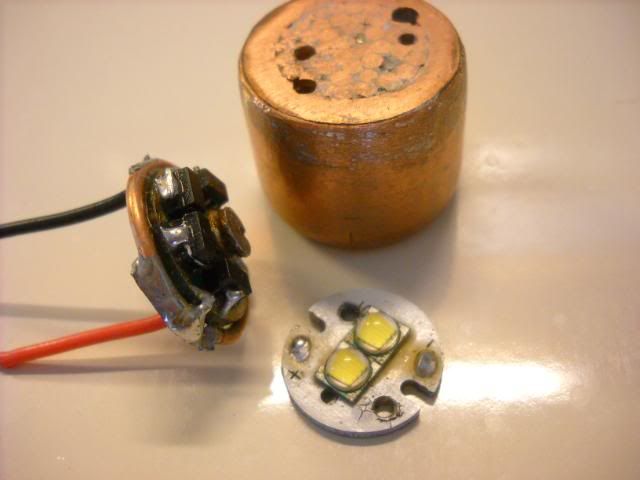
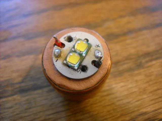
I used a copper penny, filed down flat and soldered to the slug with the monster. I'm not a metalwork guy, so I don't know what lapping is...
Trouble is, now these are pretty underwhelming now that triple XML's are common! And I add four additional AMC's to the boards to up the current. The 3 XPG's will do 4.2A with an IMR cell.
The 4000K neutral is still my favorite tint. I finally built up a triple-triple XPG Mag with 3 of the neutral boards. Now that's a vicious flooder!!
Glad others are seeing this thread now!
Rich
Lapping is what you did with the file making sure to get the surface flat as well as smooth. A copper penny doesn't have much copper in it. Just enough for colour. Might be better to cut open a section of pipe and hammer it flat then file it smooth or cut the end from a 3/4" cap. I keep odds and ends of copper flashing around for this. I found a thicker guage at a local salvage yard that comes in handy too.
Every light I've made has been upstaged. Darn. Guess I'll have to make a new one. Thanks for sharing your work. I find working with copper to be pretty straightforward and enjoy reading " plumbing mod" threads.
Pre-1982 pennies are made up of the good stuff.
Later examples are largely zinc, at the behest of the zinc lobbies. Nickels have a similar history.
Rich, I did the same thing to a 2.8A board - a total of 12 AMC's for a total of 4.2A- to drive 2 x XML in parallel on the same board (a "Linger special w/XML). Problem is, I got a lot of flickering from that setup. The emitters were screwed down onto a large custom copper sink, so I know overheating was not an issue.
I had also tried to mod another 2.8A board with 2 extra AMCs to drive a single XML and also had the same flickering issue.
I double checked all solder joints which looked fine. I tested with fully charged 26650 IMR, as well as 18650 Lion. Have you seen anything like this in your experience?
Hill
There you go. That's what I use.

really? this whole time i thought it was because of the rising price of copper. damn those lobbies! i want cane sugar in my Coke! and i want copper in my pennies damn it!
I can't believe you actually defaced an US coin for the sake of a light. Though a nobler cause I cannot imagine for that bit of copper/zinc, whatever. By the way, did you check the date before you swung the hammer? I knew of the change but did not know the year. Thanks
Hill, any chance you can post a pic of your drivers? I am working on a few versions of this and am curious about the work done by others. I plan to stack the boards with a copper disk( at least 2 cents worth) AA'd between each board and fitted into a custom pill (the propane torch kind of custom). I'm still very inexperienced with these drivers but I think I read a post that they can flicker due to excess heat when using large imr cells that don't sag. You may need a small value(.25-.33 omh) 3-5 watt resistor to drop Vin closer to Vf. I'd like to learn whatever you find out. Thanks
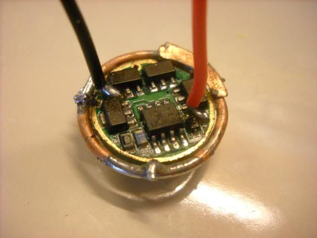
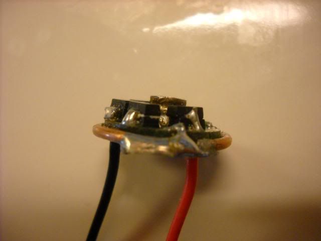
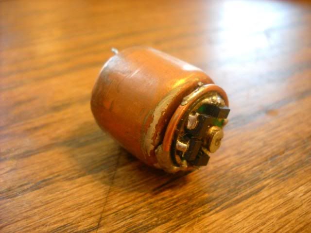
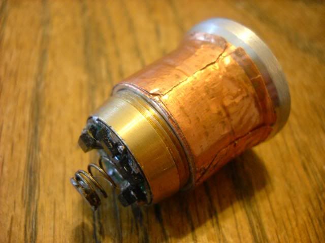
Here is the 12 x AMC driver, copper heat sink, and 2 x XML in parallel. I have since desoldered the setup since it wasn't working properly. The copper slug weighs in at ~ 60g. The copper ring around the driver was my negative battery contact. It was able to pull ~4.5A on high, but it wasn't stable. I also tried powering with 4 x C NiMh cells without much luck - still got flickering issues.
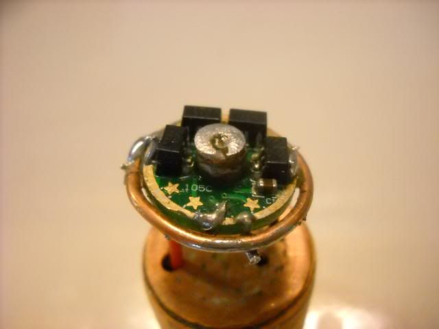
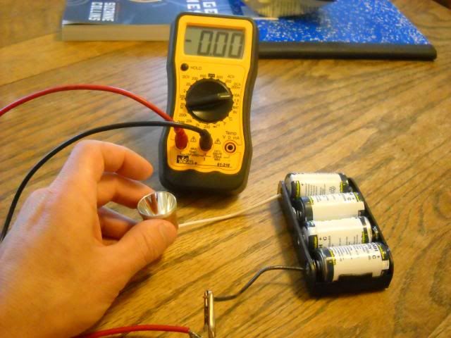
Prior to the previous setup, I made a P60 dropin with 10 x AMC chips driving a warm (4500K) XML. I also had flickering issues with this module, but just tried it again today with the 4 x C NiMh cells and it worked fine. Pictures show current draw below with no flickering, although the pill got hot pretty fast and started to cook by hands.
6 x AMD chips on bottom (2 stacks of 2)
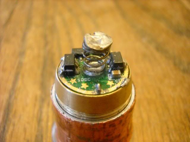
Copper foil wrapped for better heat transfer
No Power
Low
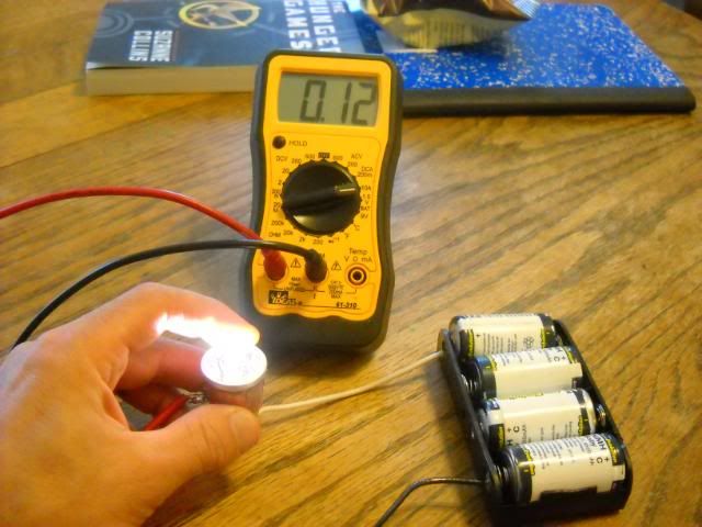
Medium
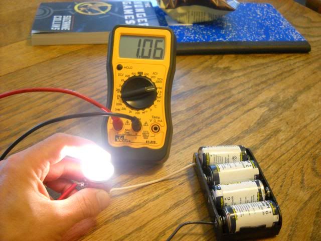
High
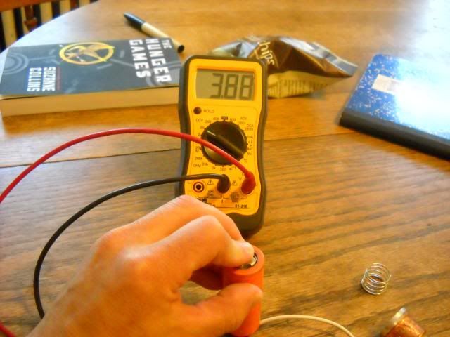
Thank you for the reply. The pics didn't come up but decent nimh c cells should not have any trouble with 1-2 c load for at least 50% of the discharge cycle. I have heard of this flickering before and I thought it happened as the amc chips began to overheat but my memory suck so I could be wrong. I was looking at PDF's for nimh cells this afternoon which is why I don't think 4 cells is the answer(without a resistor). When you say "not stable", are you refering to the flickering? I looked at the XML forward voltage vs forward current curve and at 2250mA the XML Fv is ~ 3.2V or so. The chips have to burn the excess voltage, with a full imr cell and allowing for the drop across the the driver this adds up to ~.85 V x 4.5A x4.5A = 17.2 watts.
(WRONG only 3.8 watts, but still high) .85V x 4.5A = 3.825W
With 4 x hot nimh's (>1.2V) the drop across the driver might approach 2V making for some very hot chips. These drivers are still new to me and I am just passing along second hand knowledge but the math "looks" right and if it's not I'm sure someone will correct me. From what I've read so far, the best option I've seen is a small value (.05ohm .2ohm, depending on Vb), high wattage resistor to take some of the heat. You might even be able to use a on1-on2-on3-off clicky to switch different r-values as Vb lowers with on1 @ .15 ohm, on2 @ .075 ohm and on3 0 ohm. These are ballpark values that can lower the input voltage from .5 - 1V but it's late and my head hurts. I know it's been done and I am determined to join that group. The price will likely be an increase in the size of the fried, desoldered, or unused parts pile. Don't give up. You may be only a $2 part away from lumen nirvana.
Pics updated - I moved them in photobucket after posting - Duh!
Thanks for the advice about adding resistors. I recall teckjunkie having issues with a 4 x XML build be driven too hard with NiMh cells, but his setup was using 4 x 2.8A boards so not sure if the same issue of excess heat was true.
Yes, the "unstable" comment I mentioned was in regards to the flickering. It would start nearly moments after power up, and I did in fact "touch" the board to see if it was overheating. It did not feel warm to me and it was also mounted on the underside of that massive copper heatsink to help keep it cool.
Thank you for getting to that so quickly. Nice clear pics. Is that a 1/2x3/4 slug or a 3/4 pipe cap. The difference being if you put the leds on the closed end of the cap, you can solder in either a short section of slug or pipe and recess the driver. This would allow you to AA another flat piece of copper directly to the tops of the chips and to the cap. My concer is the "path to ambient" for the heat generated in the chips. The distance between the heat source and the sink metal has to be minimized. Or maybe flip the driver over and AA the chips directly to the sink. I seems likely the resistor has a part to play in matching Vb to Vf but I have not yet found out at what drive current it becomes critical. I will be spending some time on this issue when I'm at home this week and will post some pics of what I have in mind. There's so much creative work being done with these drivers it is hard to remember where I saw some tidbit.
Thanks again Hill for showing me your work and by the way, Dorpmuller, nice find and thank you for starting this thread.
The copper sink is just what Rich used in his triple - an end cap filled with cut sections of copper wire (~12g) and solder melted in to fill the spaces.
The mass is there but it looks like all if your amc chips are separated from the pill by the thickness if the driver. The board Rich is using is running at a lower current which is where you are generating the extra heat. You have a lower current through each led but the current through the driver is higher. The most he could expect would be 3040mA with 380 bin chips where you have documented 3880 mA. Plus, at the slightly lower current through each led, the chips have more excess voltage to burn off. I think the drop across the boardis~ .12V so for Rich he has Vb - Vf - V board, or 4.2V - 3.3V - .12V = .78V drop the chips must burn off as heat. At 3.04A this results in .78V x 3.04A = 2.4 watts and might be as low as 2.2 watts.
Yor setup has a lower Vf(@~2A) = 3.18 so 4.2V - 3.18V - .12V = .9V and at 3.88A means .9V x 3.88A = 3.5 watts
With 4 nimh cells this will get worse. A resistor that lowers Vb by .5V would bring you in line with Rich's setup. Something like V=I x R or R = V/I , so R would be .5V/ 3.88A= .13 ohms. The resistor would need to handle .5V x 3.88A =1.89 or at least 2 watts. A lower value resistor will mean more time that Vb remains above Vf but means more work for the chips. This is the tradeoff unless you can switch out the resistor as the battery voltage decays.
The voltage drop has to occur somewhereif the chips can't handle it we move it somewhere else.
I need to edit the previous post as I was way off on wattage
I really get lost in the math stuff...but it sorta makes sense and at least explains why I have been having issues with the 12x AMC high current setup.
If the issue is overheating of the driver, why then do I see the flickering within moments of power up? The driver is not hot to the touch when the flickering begins, so I'm puzzled. If overheating is the culprit, the driving should feel hot, but it doesn't. I also see flickering at the lower settings (med, low).
Apologies for sounding ignorant on this. It seemed like this would be relatively easy...just kinda "plug-and-play", or in this case, "stack-solder-powerup".
I'm no theory guy either... but the only time I've had flickering is with stars that I've tried to reflow emitters on to.
Haven't had any problems with any of the triple Mag setups I've done, Techjunkie style, with heat and 4 NIMH cells.
Rich
My math is suspect to. I can puzzle my way my way through theory as I'm doing here with you, but I'm still short on experience. One other difference between the two setups is the added chips on your board Hill. I'm no expert and it looks to me like you did a nice job adding them but it is possible to damage them by overheating. Not trying to be critical, just looking for possibilities. Another thing is they heat up from the inside out so the flickering might be apparent before the chips feel warm. This does not explain why Rich saw this effect on reflowed leds but maybe it is a more general symptom in semiconductors. I am guessing wildly on this but until I learn more that's all I can do. I am pretty sure the chips will perform better with, not a bigger heat sink, but a closer connection to the chips and these boards were initially used with P7 leds with a higher Vf. When used with lower Vf MCE's, resistor were being recommended. If a definitive answer is found, I'd like to see it in a nice, comprehensive thread on these drivers. I would certainly welcome input from someone with knowledge of failure modes, what causes them, and how to avoid them(that sound like a good thread title, all we need now is content).