Photos of the build and Commentary
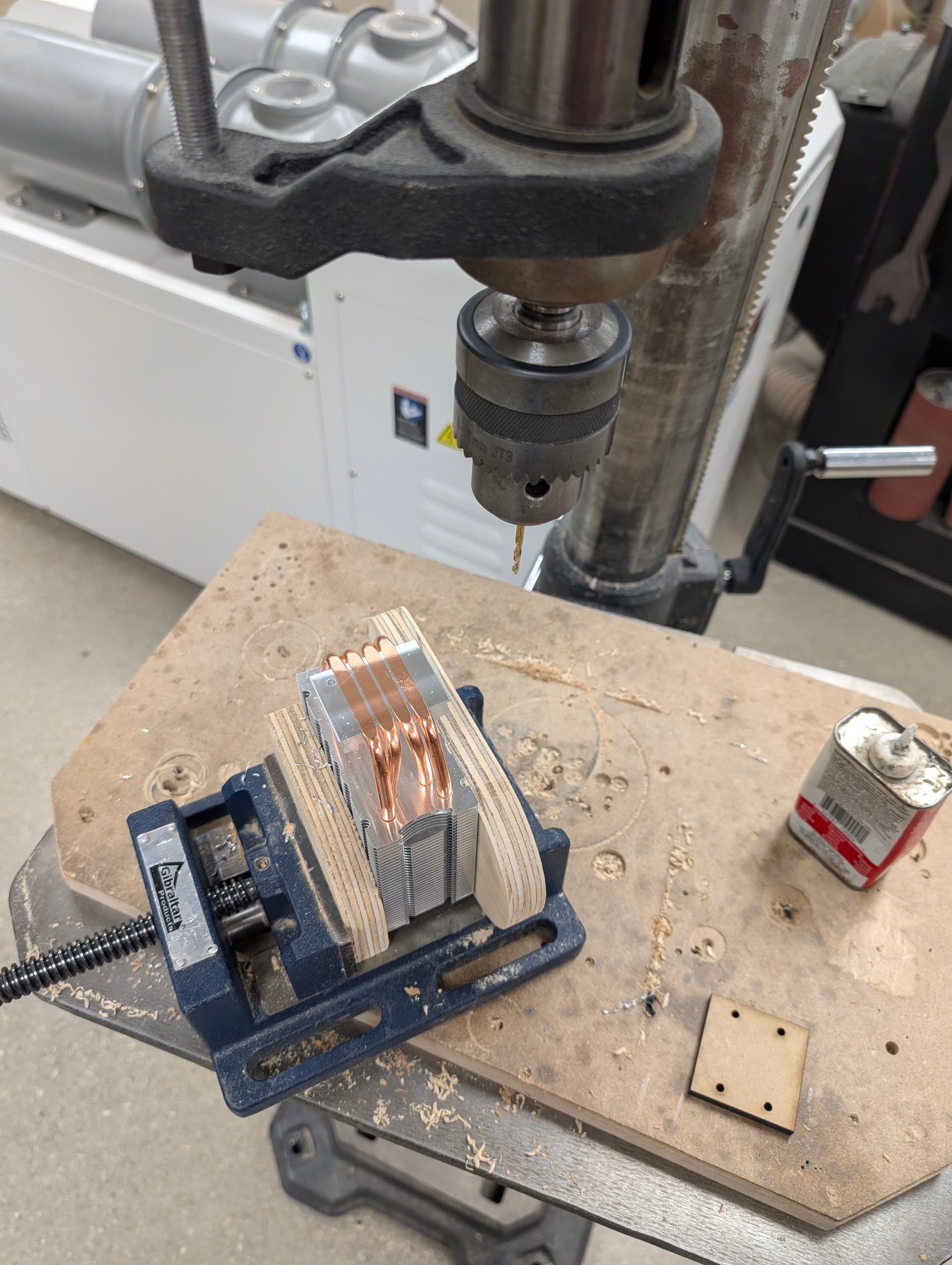
Drilling mounting holes on a drill press using a laser cut jig to mark the holes
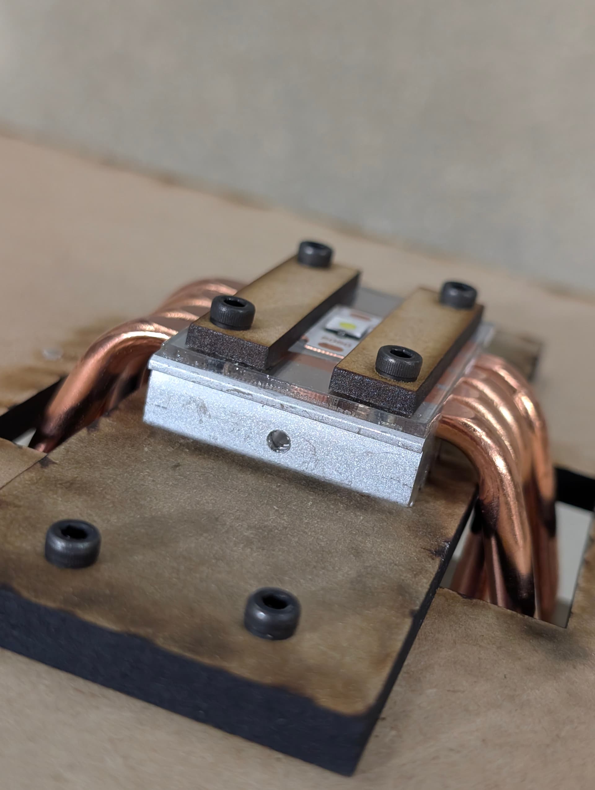
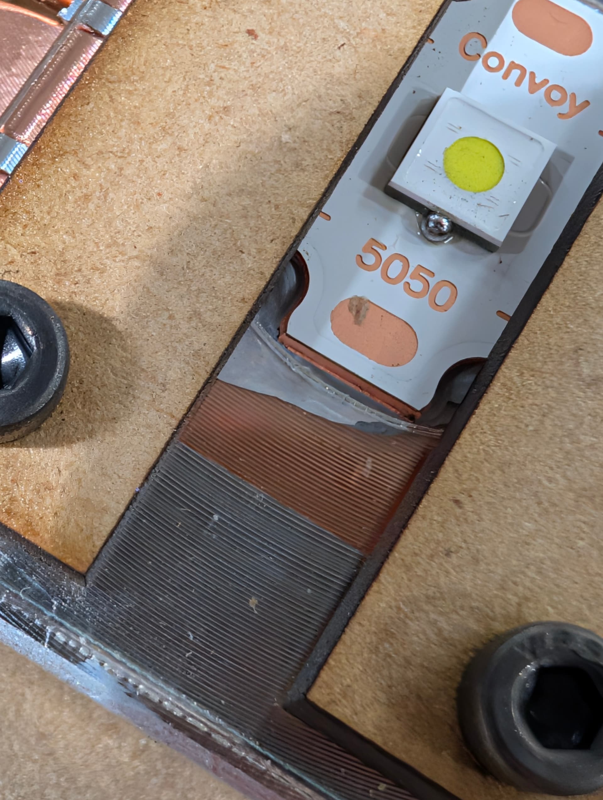
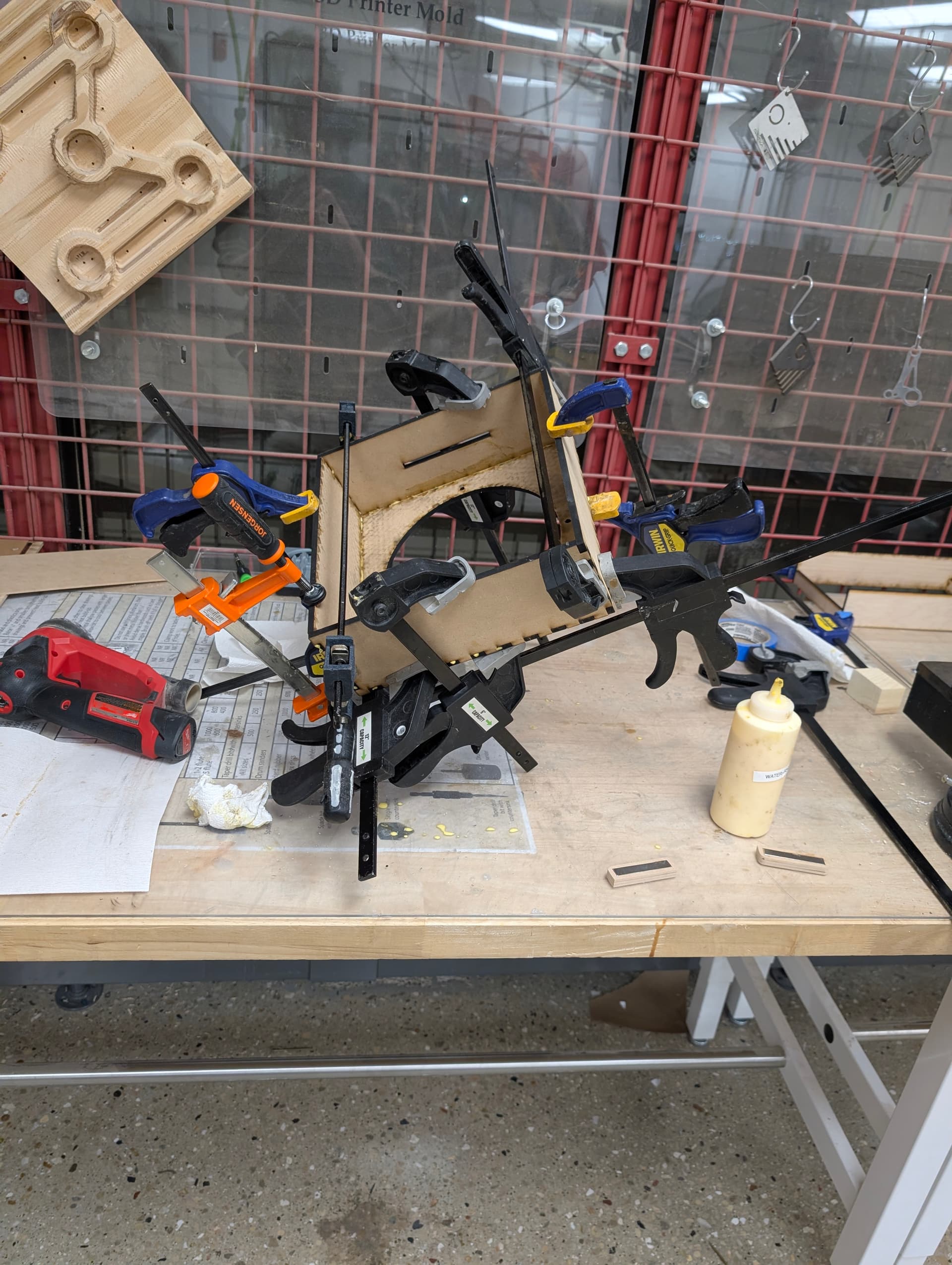
The next two photos show the LED mount, it uses 1/16 inch petg as a centering ring and two lasercut pieces of MDF secure the LED in place. The screws through the heatsink connect to a woodenn rectangle that is then bolted to the back face of the enclosure.
This is particularly unfriendly to work on as i didnt leave the builder much space for holding any of the nuts required to mount the heatsink - threading the holes would have helped but i couldnt locate the taps.
The mounting pressure is sufficient as you can see some squeeze out
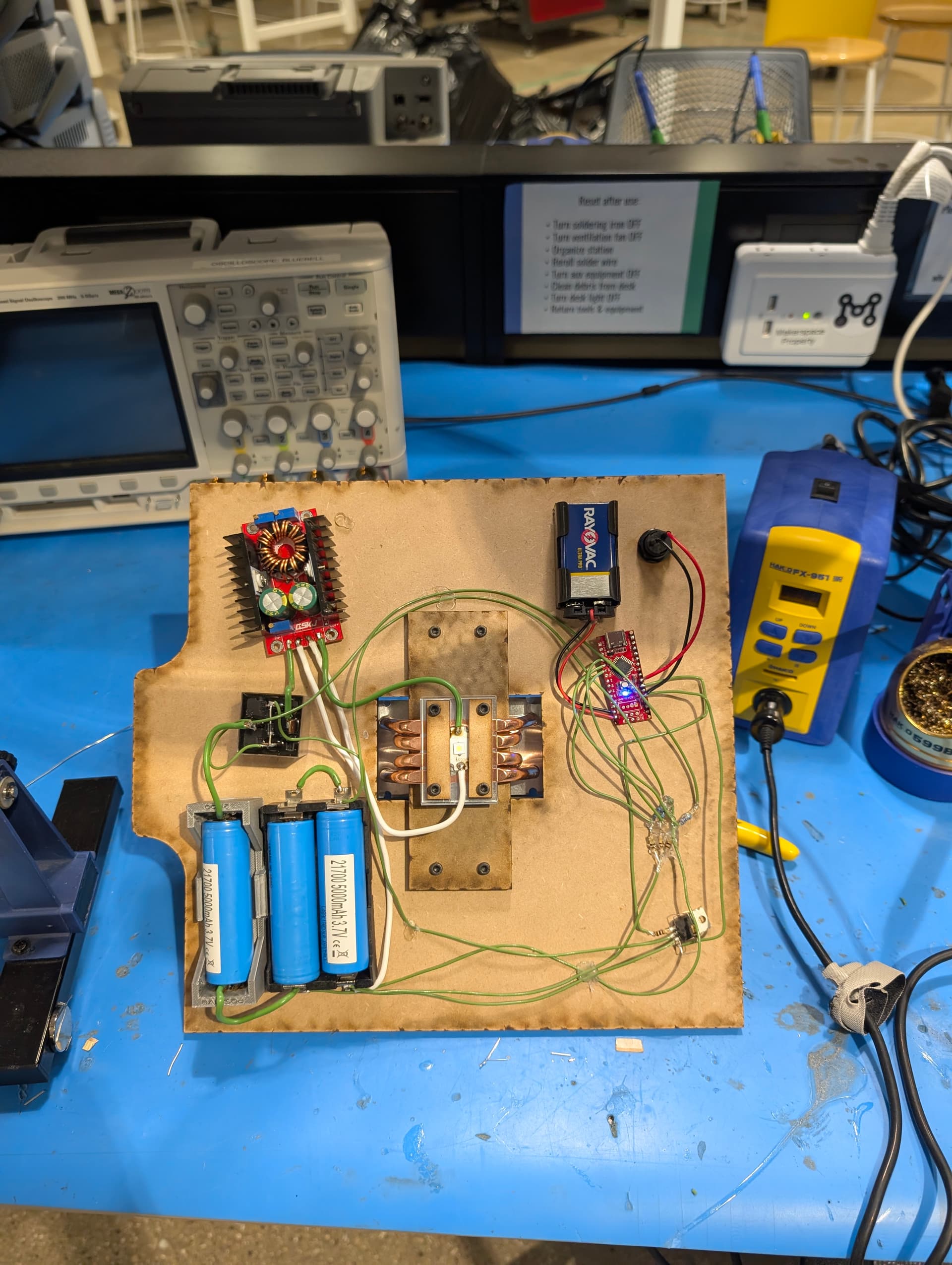
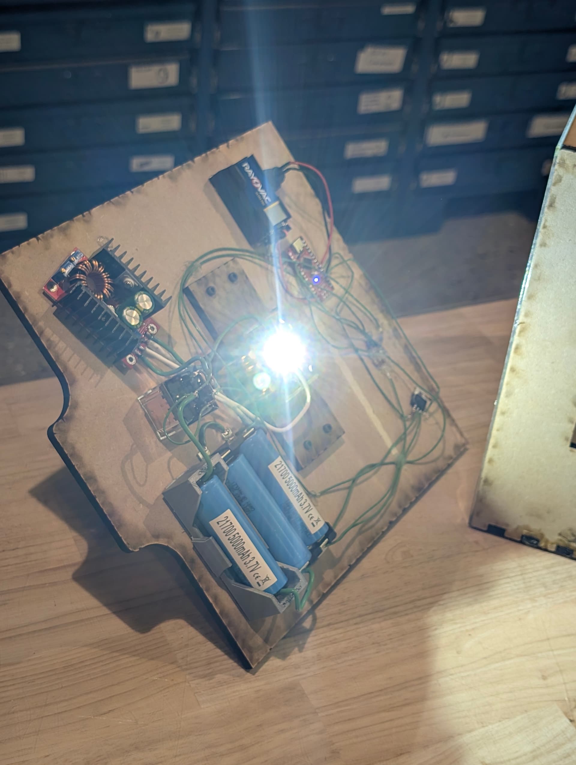
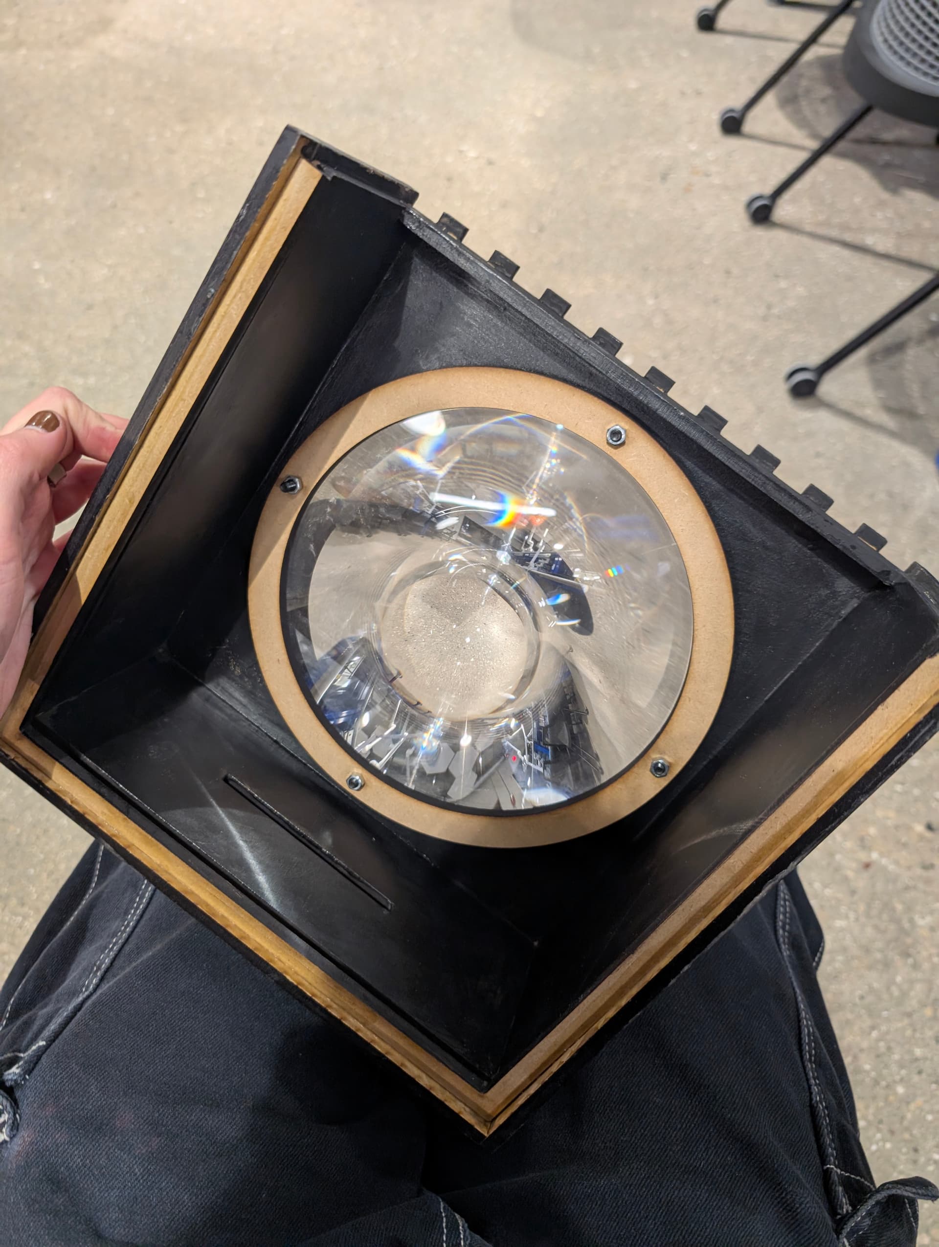
These next two show the finished back panel - all electronics are mounted here - more details on this can be found below.
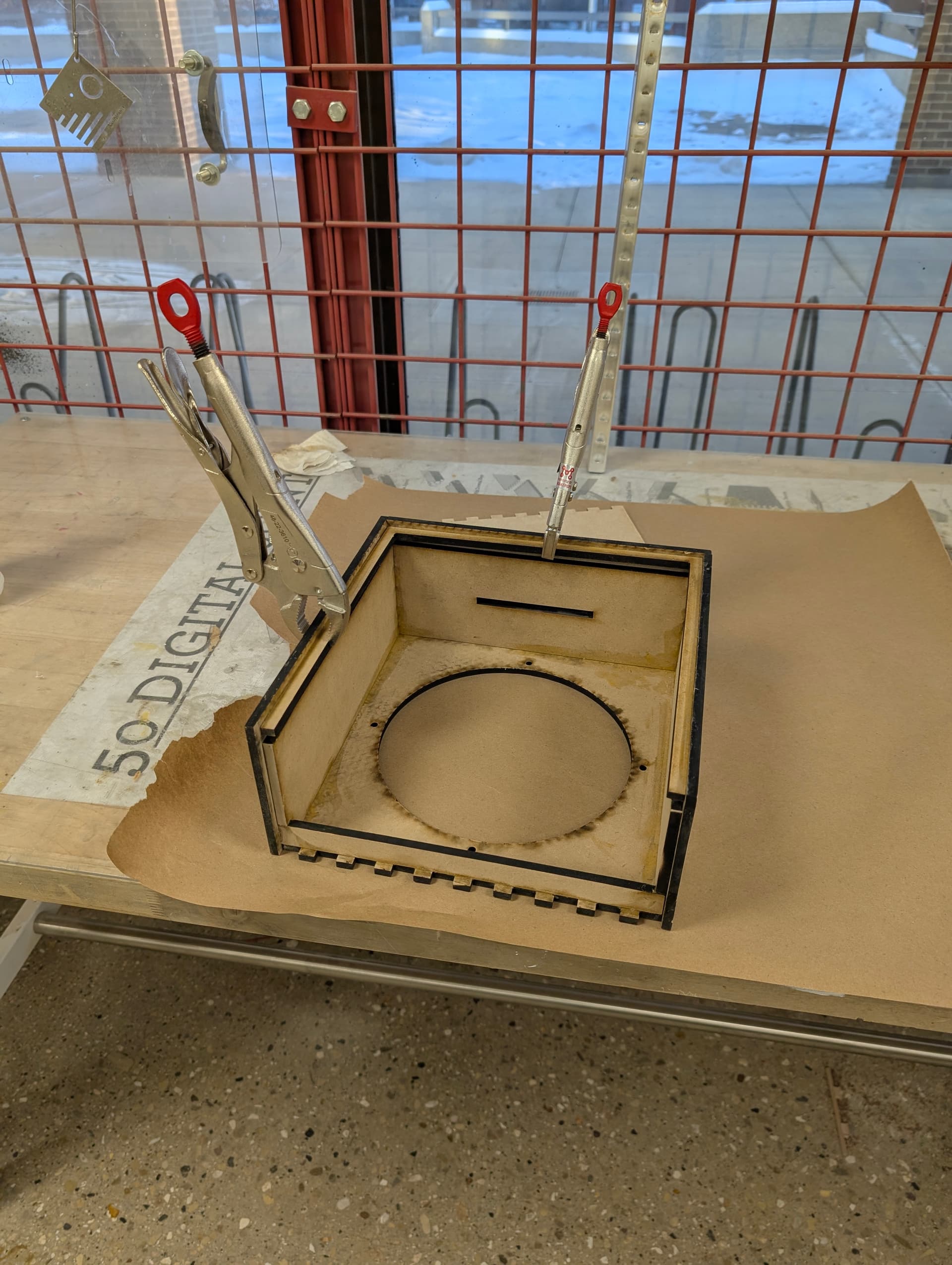
This is the first version of my design that i used for prototyping being glued together.
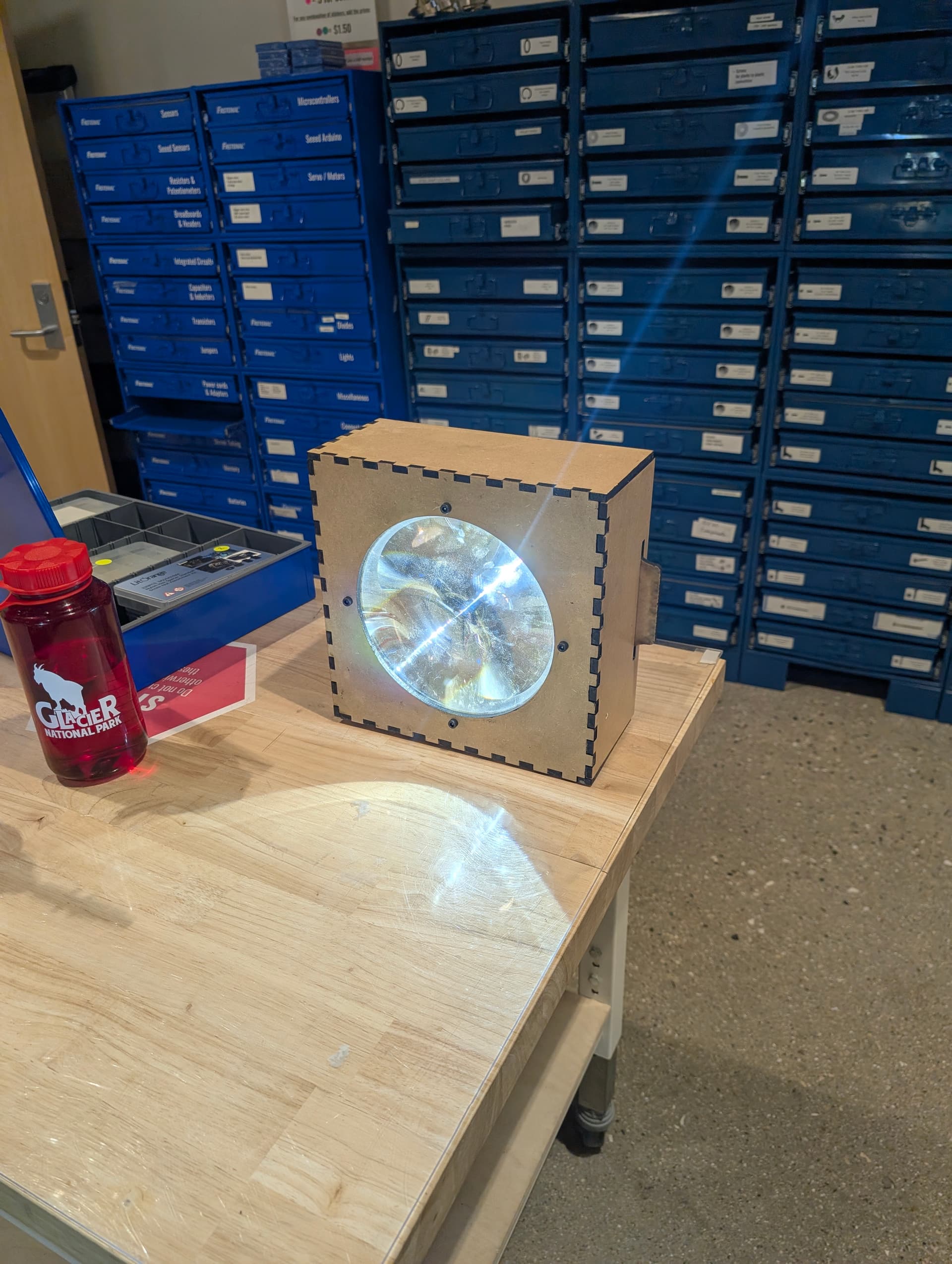
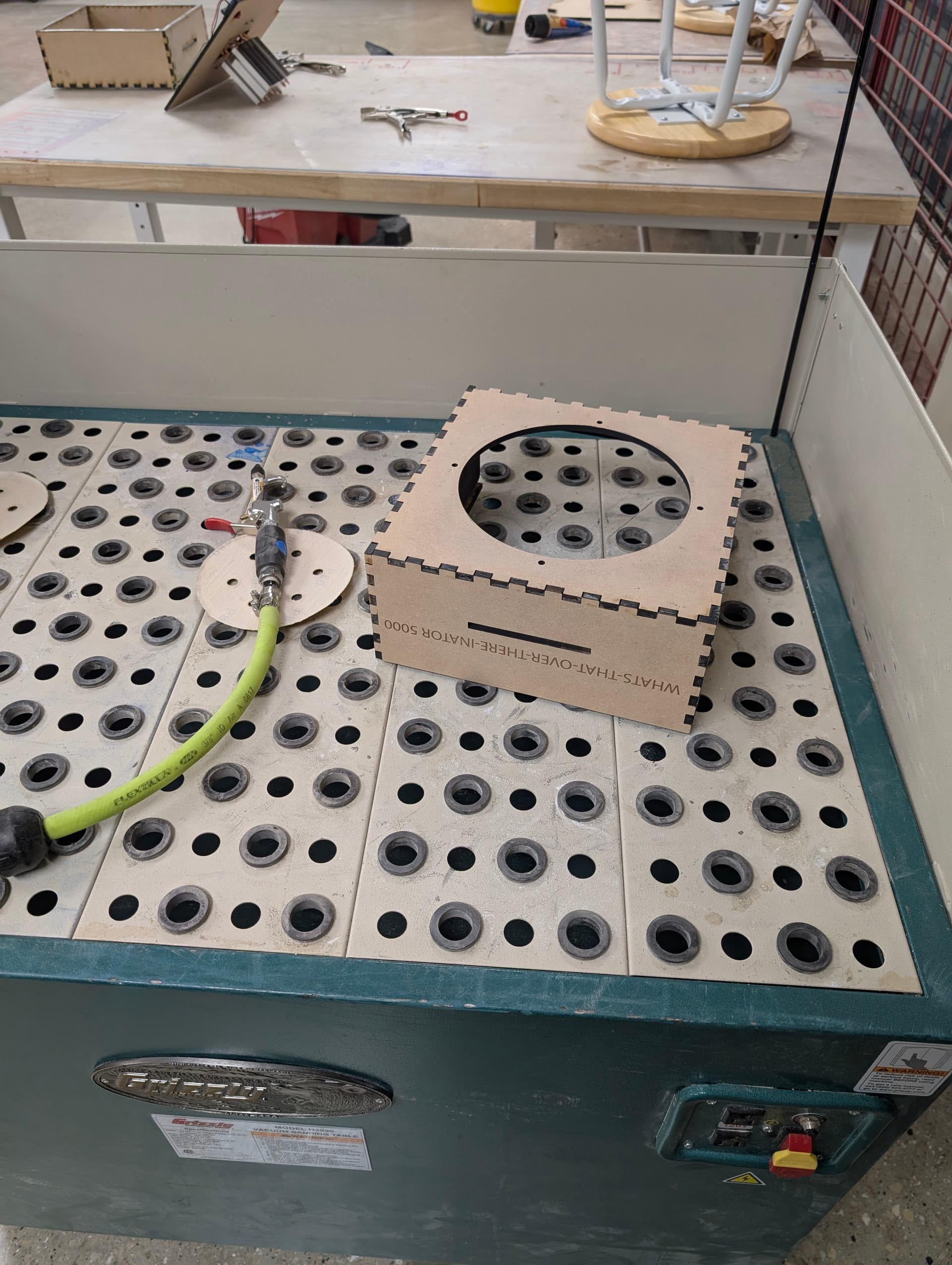
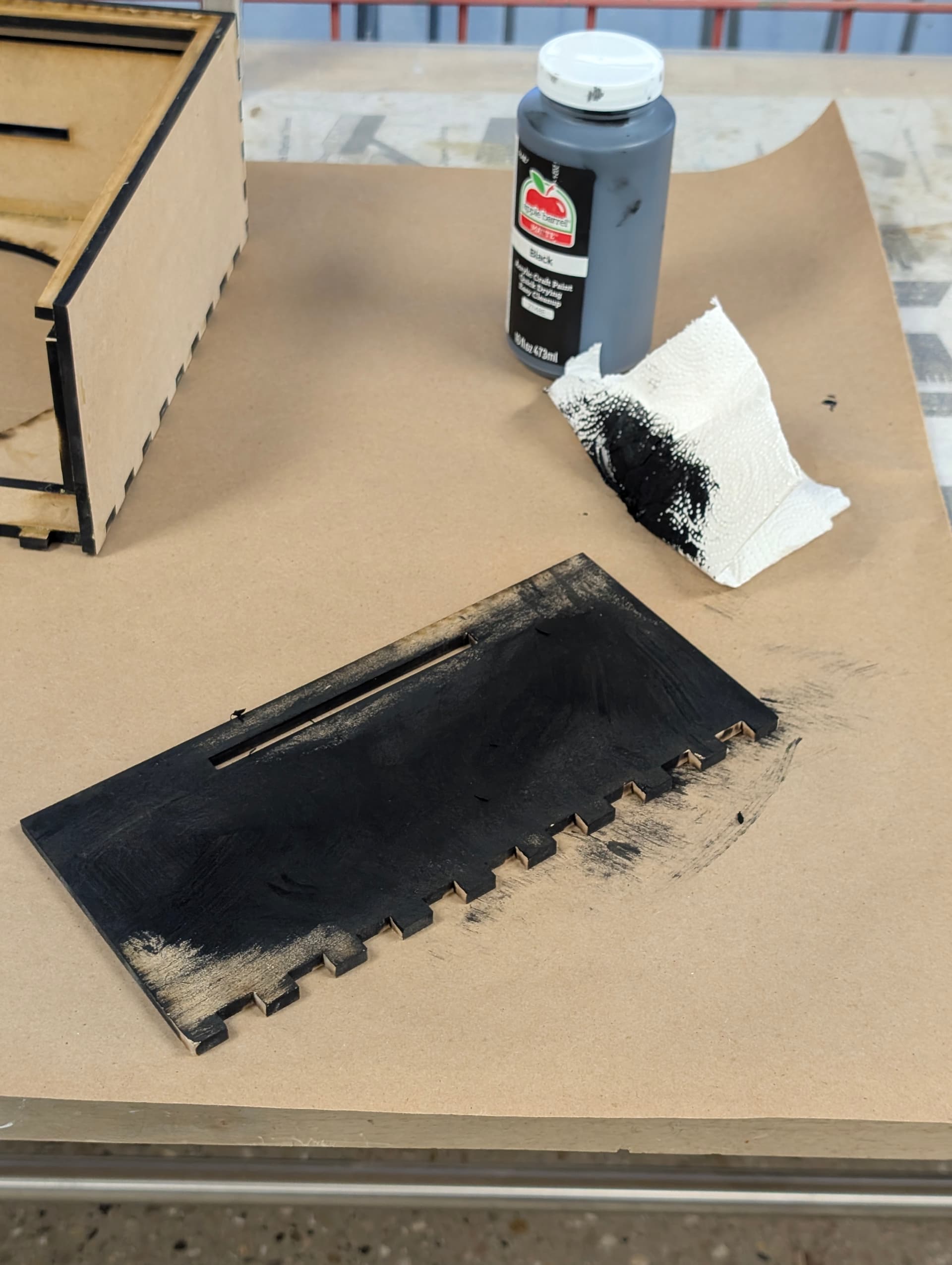
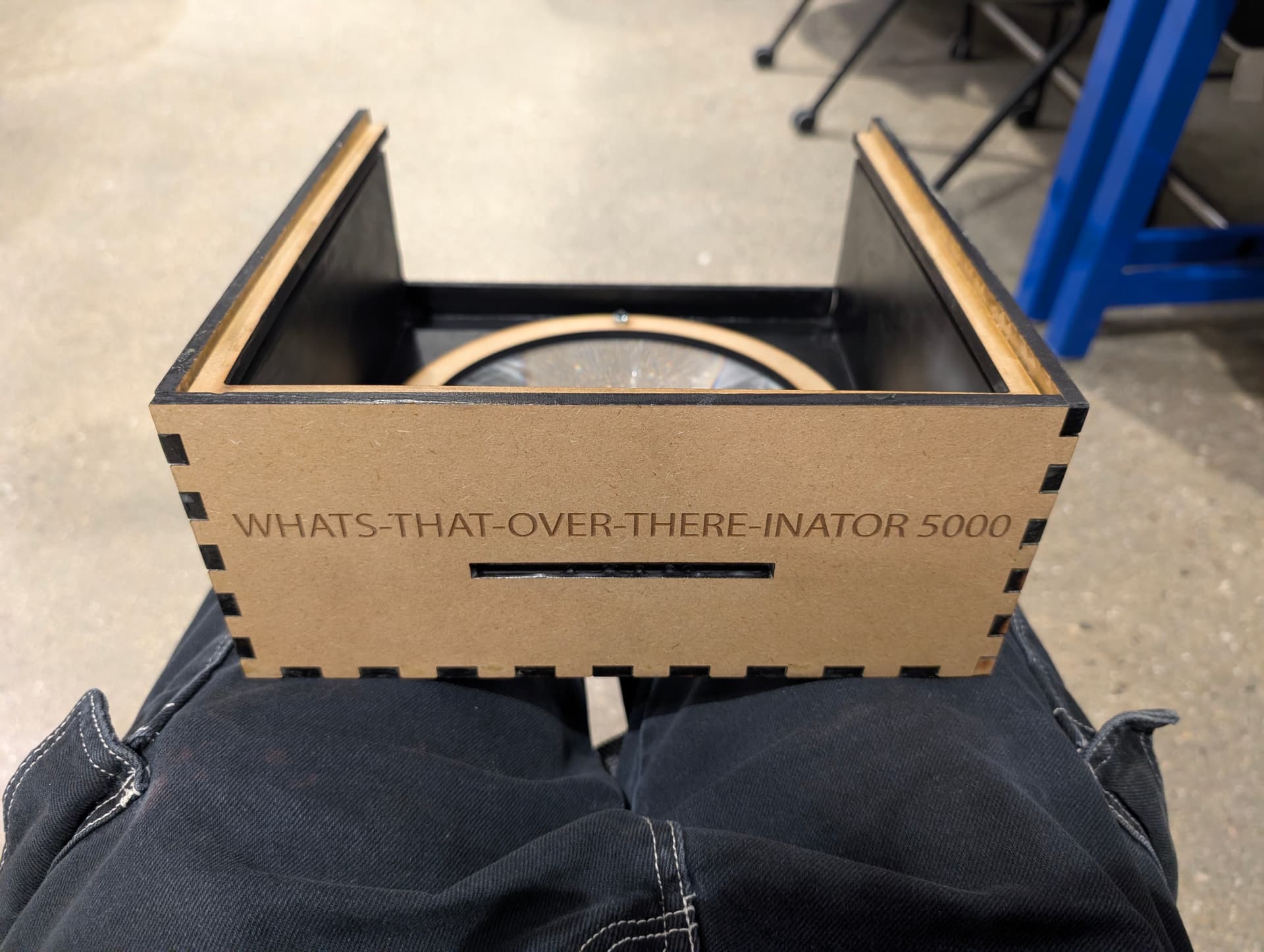
The next photos show the sanding and finishing stage of the final box. All inward facing parts were painted black and all outer faces were sanded and sealed with a water based finish - I am very happy with the achieved surface finish. I used the laser engraver to engrave the text on the front. The box is decently water repellent and i felt confident setting it down in the snow, its a very smooth finish thats pleasant to touch, though I was able to nick it with a box cutter quite easily.
This video is mostly irrelevant as I’m just cutting a test part, but its a really cool shot of the laser cutter (150W CO2 )
Parts Used
specific parts:
200mm Dia, 70mm focal length (a longer focal length would work too but you will likely end up wasting some light)
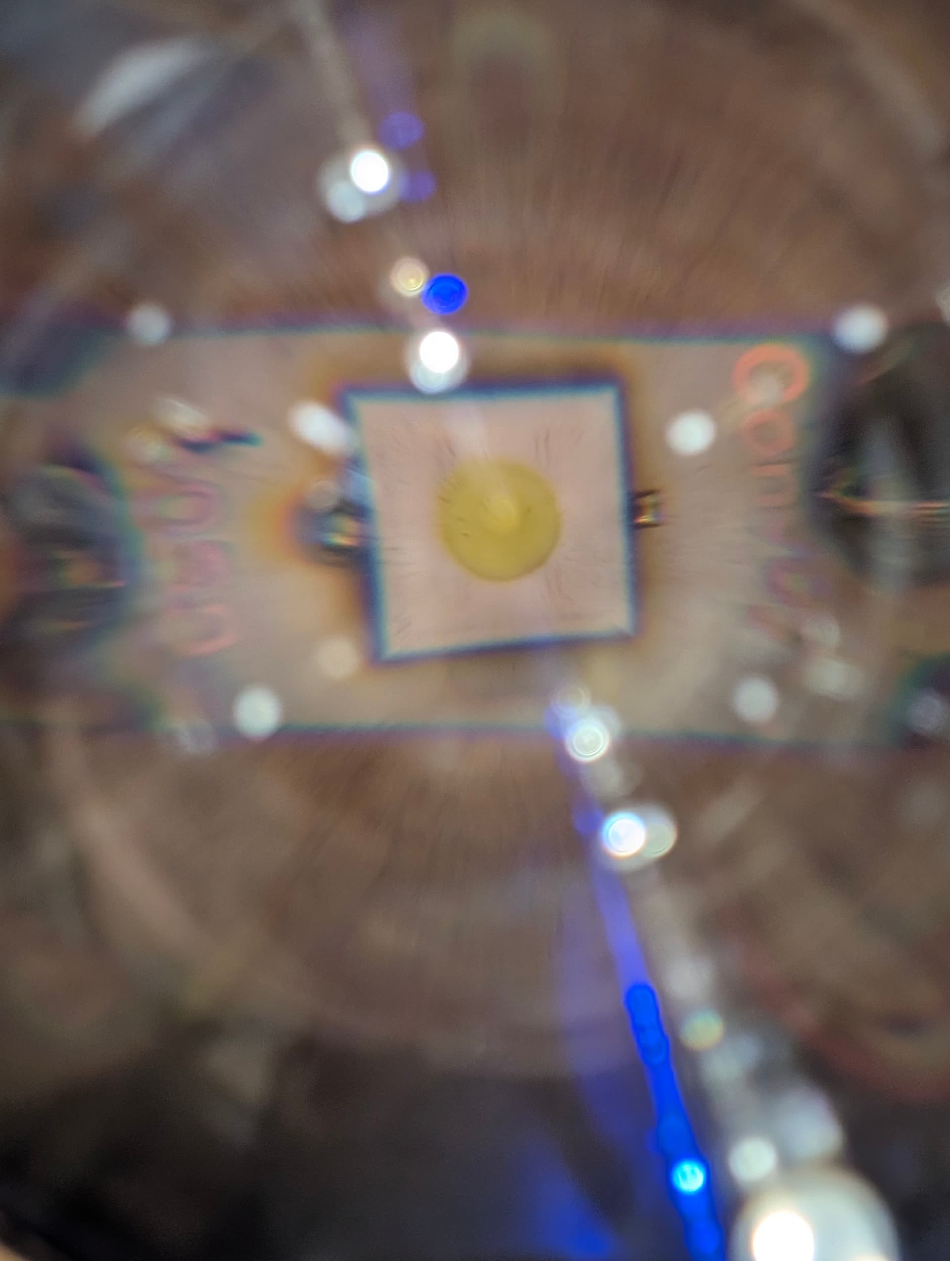
LUMINUS SFT-42R 6500K
Air Cooler (plenty overkill but i like the look)
CC CV Buck Boost Converter (would not reccomend - it has a max current of 8.5A - if you find a similar module that can handle up to 15A please let me know)
generic parts:
arduino nano
latching switch
JD1912 Automotive Relay
generic mosfet (controlled by the arduino to control the relay)
various resistors (for both a voltage divider and for controlling the mosfet + relay)
generic diode (for flyback current on the relay)
3x samsung 50e and suitable holder
thermal paste
1/4 inch MDF for entire body
1/16 inch petg (or any suitably thin material) as a centering ring
various screws
The Power Path
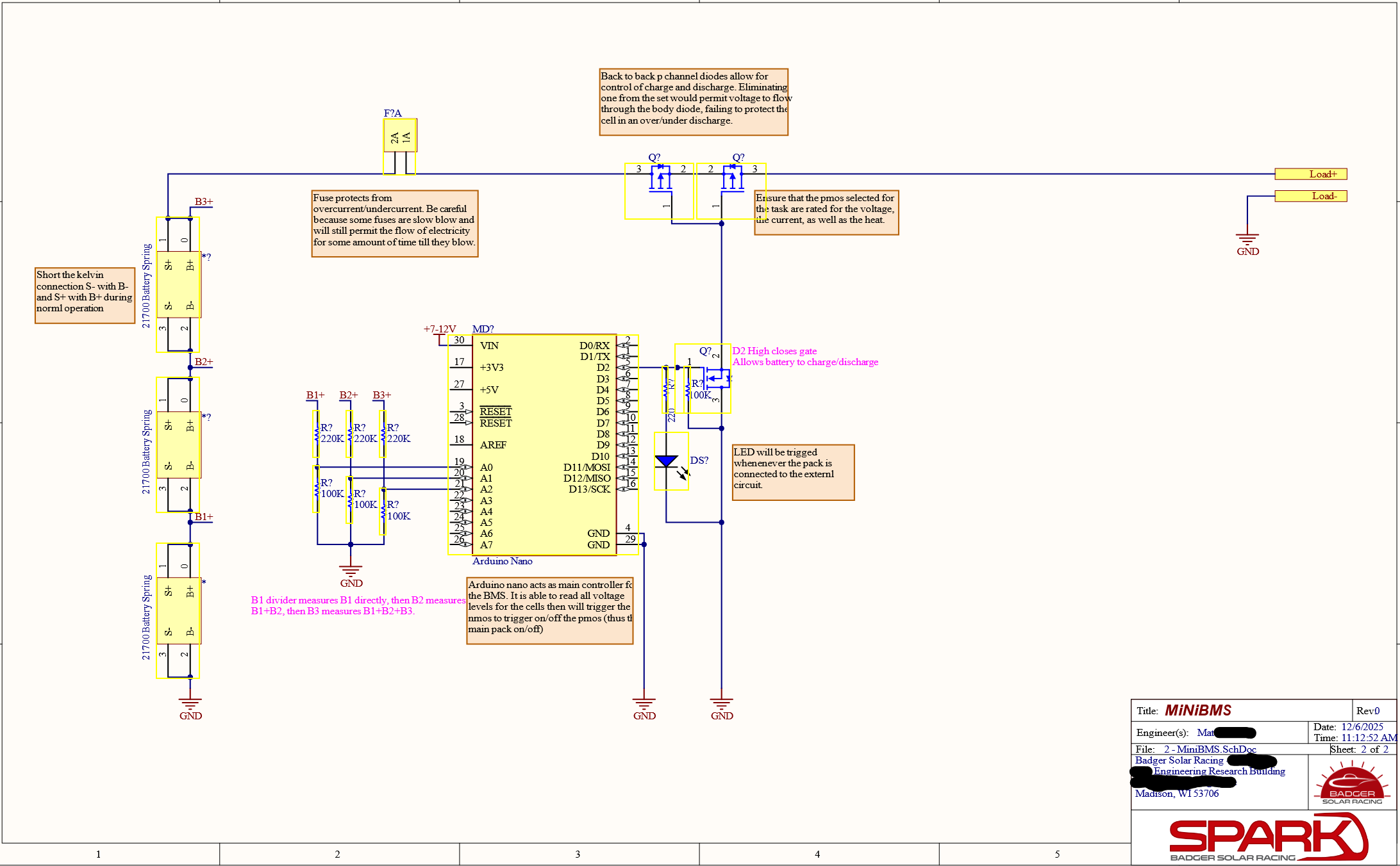
The arduino nano monitors the voltage of all the cells (further details in the BMS section) and if all safety conditions are met, it will enable the mosfet when the power button is pressed. The mosfet controls current to the relay coil. Once the relay is enabled the batteries are connected to the CC driver which is set to 8.5A with a max voltage of 3.5V.
The battery pack is 3s1p and the arduino has its own 9V supply just in case.
This CC driver is fine, but i would like to run the sft42r closer to 13A, we are around 60% brightness right now. I considered a typical 20mm buck driver from convoy but i wasnt sure how it performs thermally. The current driver doesnt overheat but it does get pretty warm.
The BMS
Huge shoutout and thank you to my friend from the Badger Solar Racing team - he guided me througb setting up the BMS and donated all the cells used, a cell holder, and a relay. He also helped me characterize a couple cells I had left at full charge for a while.
The schematic calls for using two MOSFETs, I didn’t have any suitable on hand at the time so swapped it out for a single automotive relay which was gifted to me. The code for the BMS was written by ChatGPT and reiewed by me and my friend.
How You Can Copy This Build
I havent yet figured out how to share the OnShape document as a individually editable document. When I do, all dimensions are defined by variables so you can scale it to a larger lens, different focal length, different pcb thickness, material thickness, etc.
Its a little finicky as you would need to have the exact same cooler, but thats what the “calculated offset” is for - making the hard to calculate adjustments.
Otherwise the electronics arent particularly specific, any way you decide to drive a LED will work.
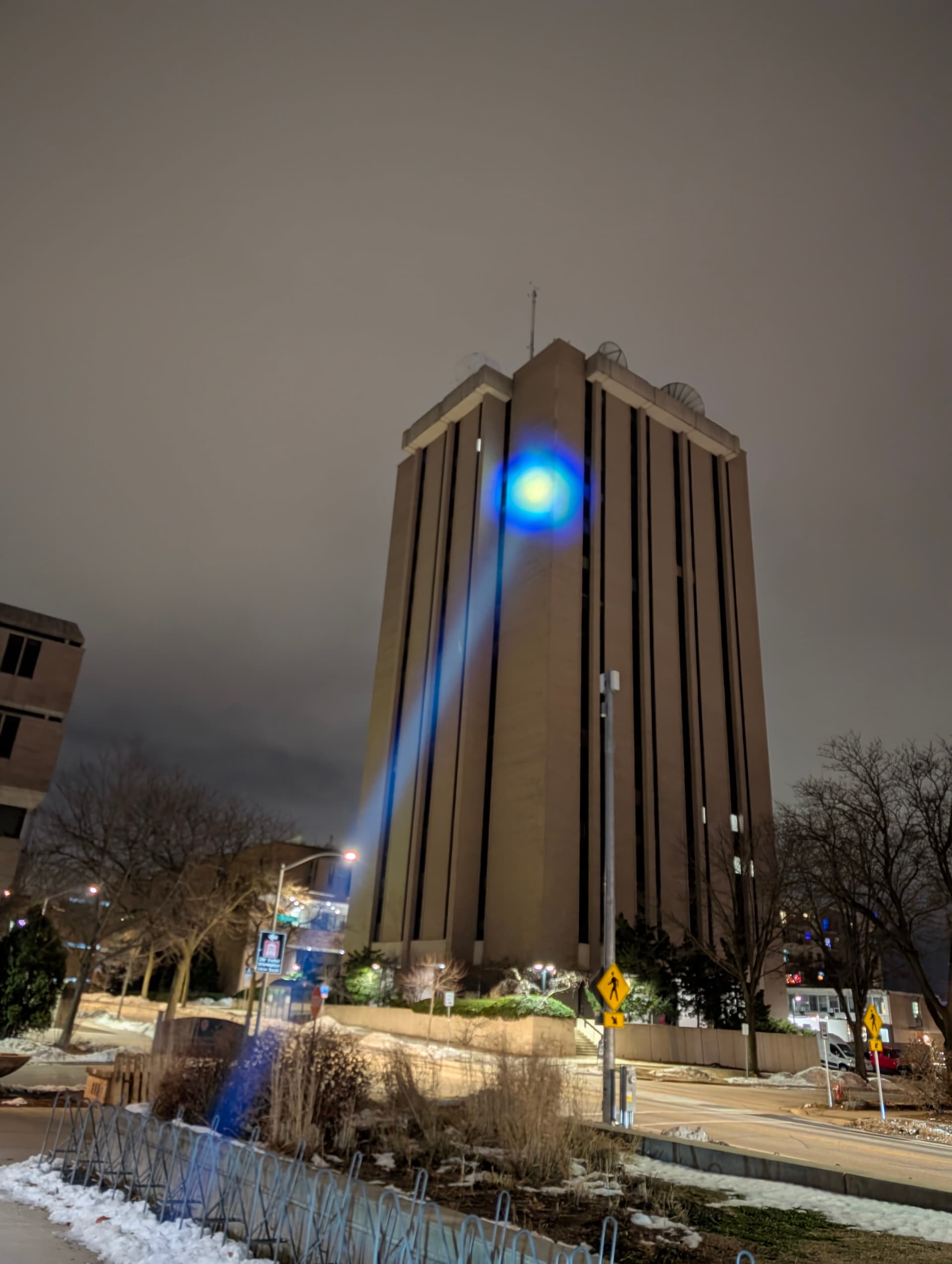
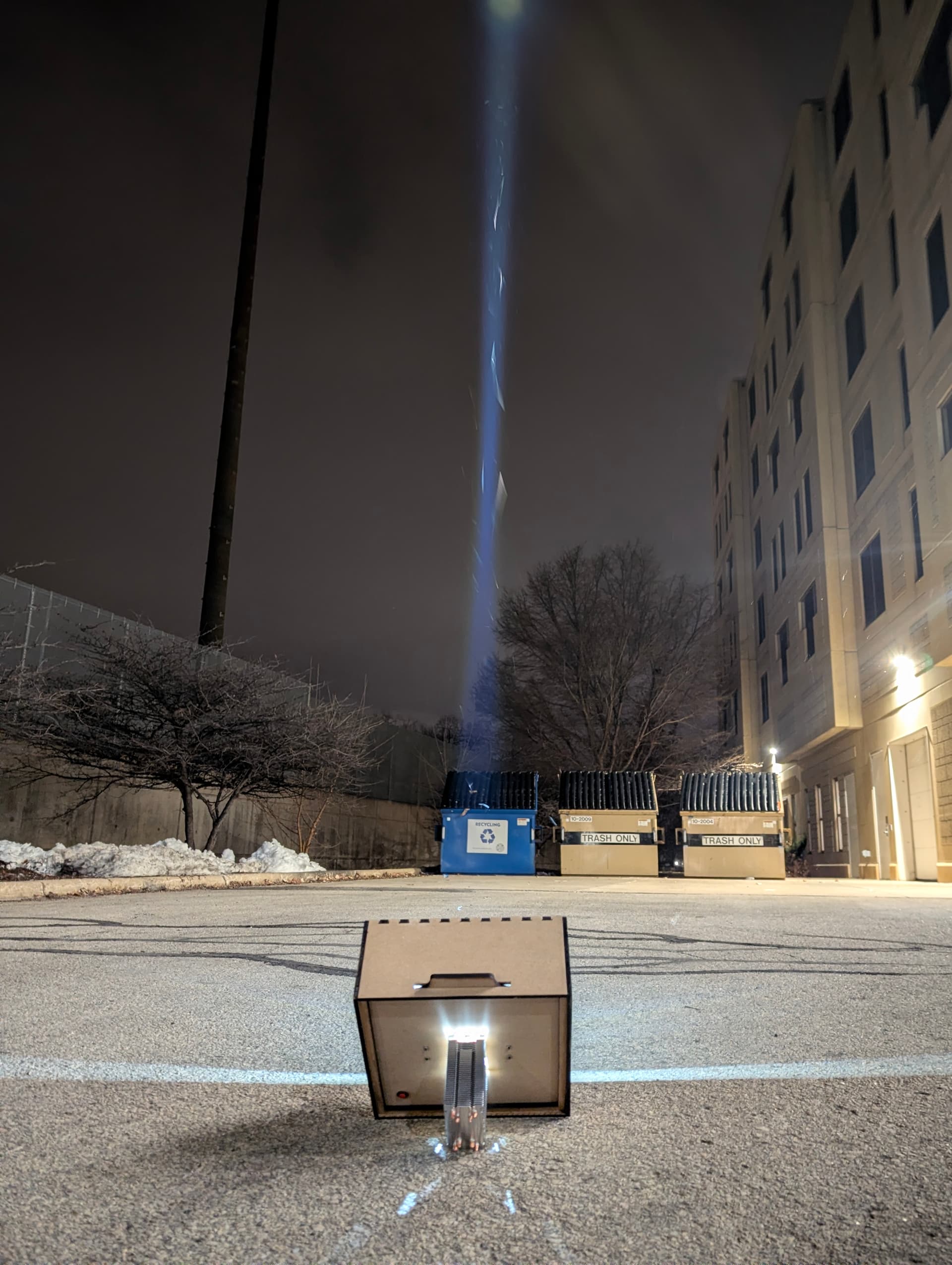
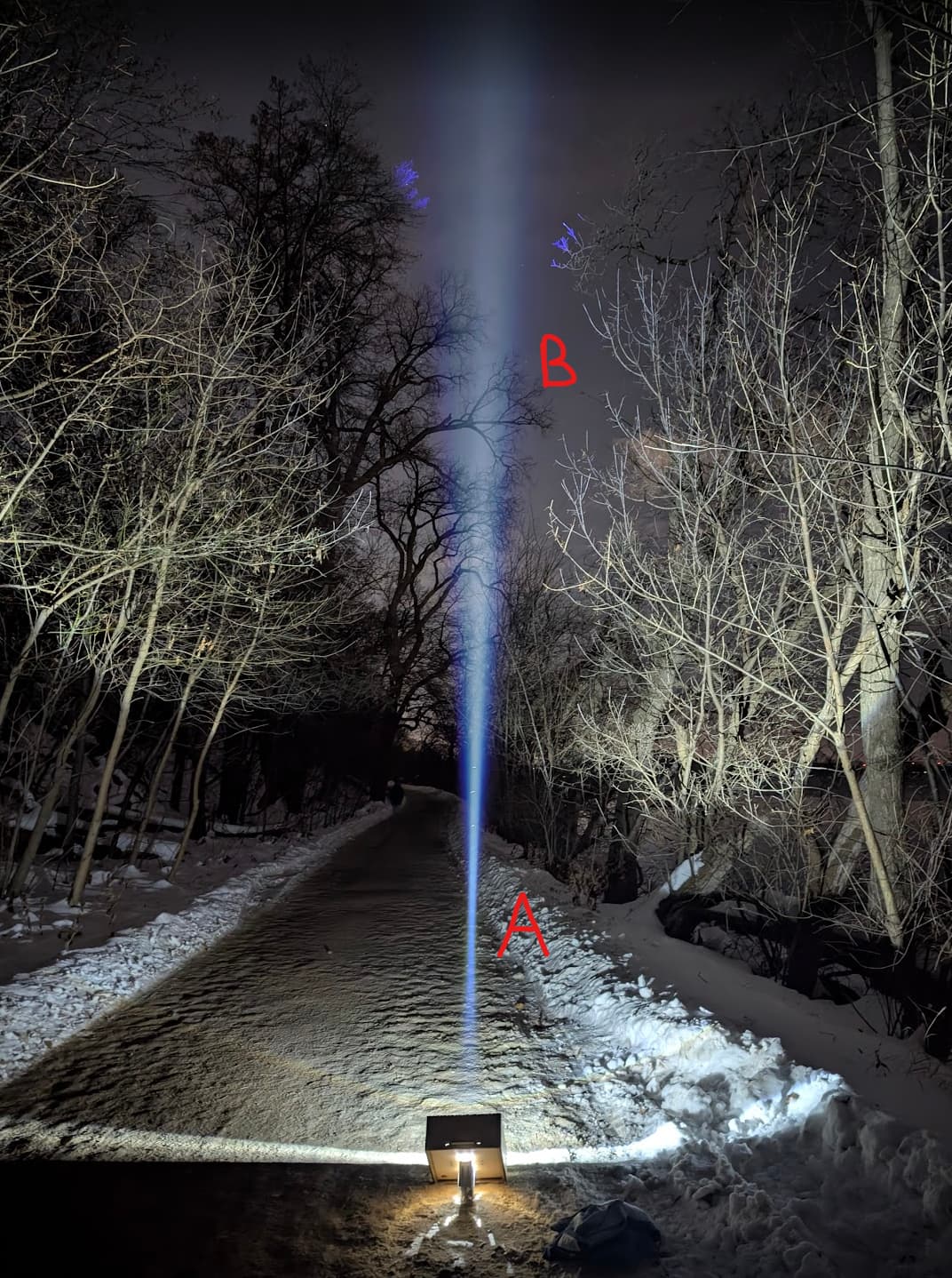
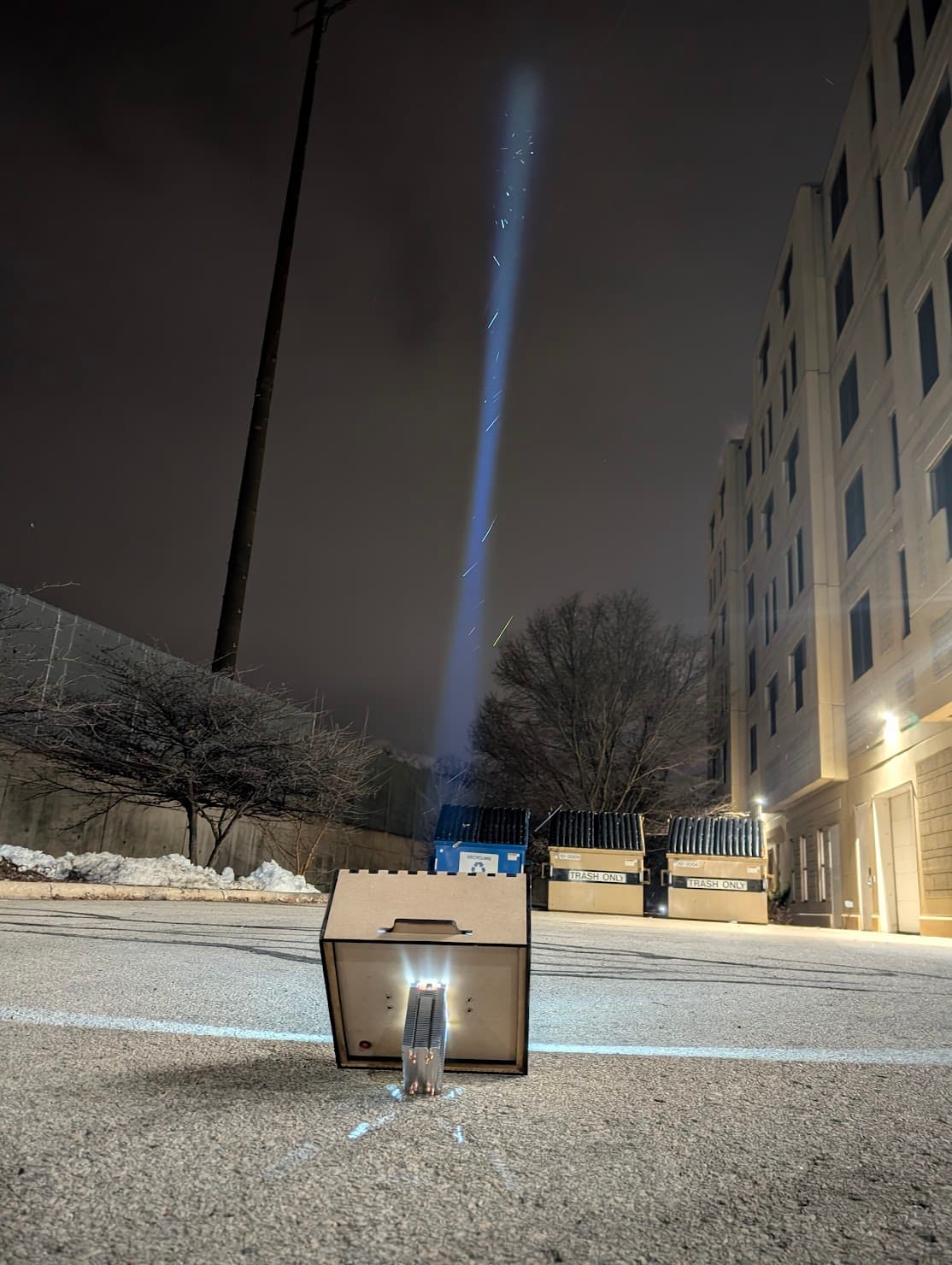
Beamshots + measurements
I had to leave the light in my dorm so I cannot take any new readings of it, the last time I measured the candela the LED was poorly focused. Although this might not mean the current value is any higher as I likely measured near the focal point of the lens.
I will update this section when im back and have access to my Opple and a luxmeter
Cool Features
I'm quite proud of some of the QOL features I integrated. Both the LED and lens have a laser cut centering ring so theyre very well aligned. This took all the guesswork out of assembly.
Additionally, having all the electronics mounted to a single face of the light makes it very easy to service as everything can be taken off and tested without any obstructions.
Having the inside painted black has done a fair amount towards reducing artifacts, although i belive the majority of artifacts comes from the LED mount relying on two 1/8" pieces of wood. At the time i created these the kapton tape was out of stock, had it been available, I would rather have used sheet metal.
A side effect of the CPU cooler sticking out so far from the body of the light is that it can stand freely without a tripod horizontally or towards the sky. You can see this in the beamshots.
During the design phase, a lot of my coworkers asked if i would make it a bat signal, after being badgered about this for almost two years now, I relented. One face has a 1/4" tall hole for inserting negatives. the lens can be defocused by adding a extra spacer. Combined, this creates a larger spot with a decently sharp image cut out from out (in theory).