Modding guide
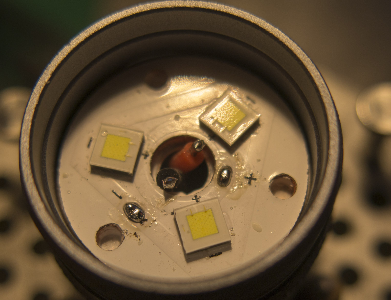
First remove the retaining ring, lens and optics
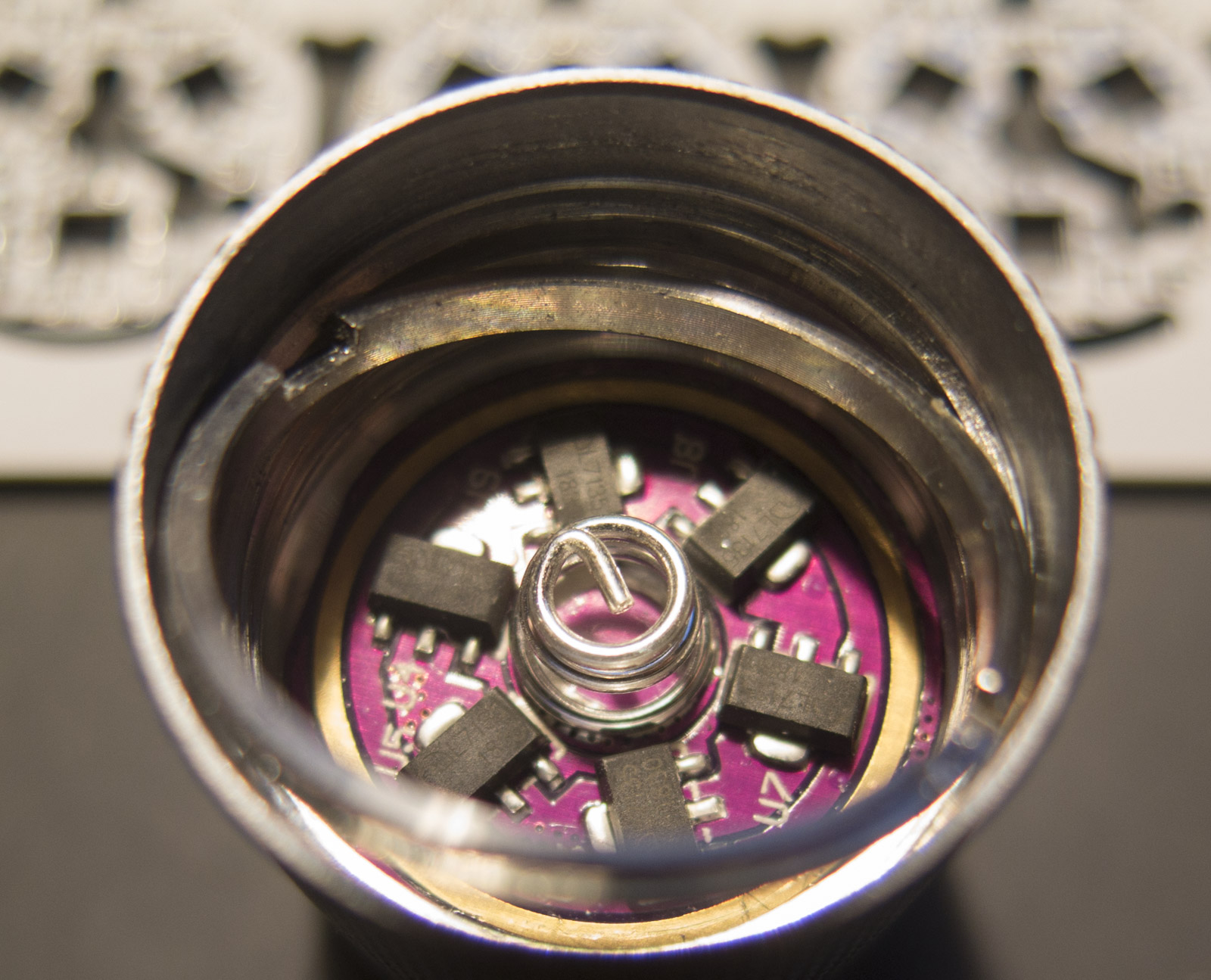
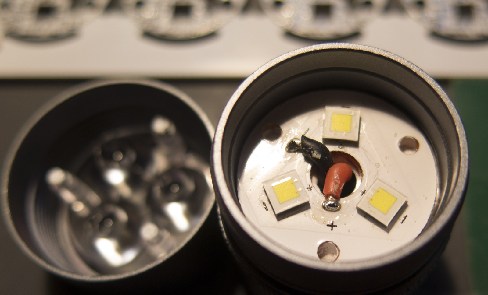
Unsolder the MCPCB wires and pull the driver
.
Now we got 2 options
- use the MCU with Aux support firmware flashed, to control the Aux board (ON/OFF/blink/LOW)
- use battery voltage to drive the board without MCU control
in the second case simply ignore the optical nerve connection and do a bridge from MCPCB+ to aux board +
.
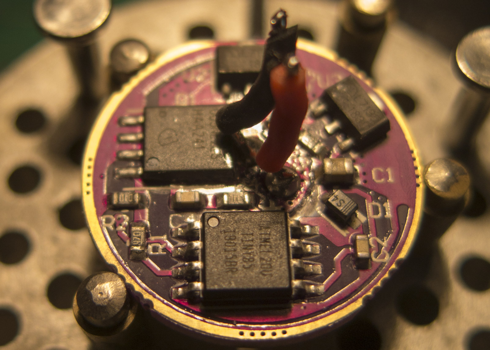
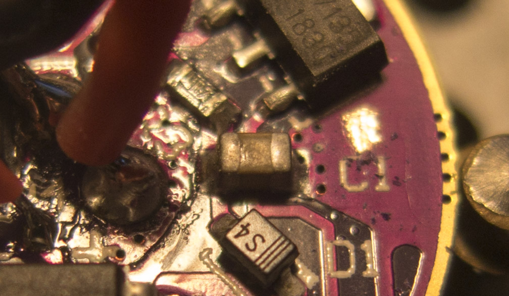
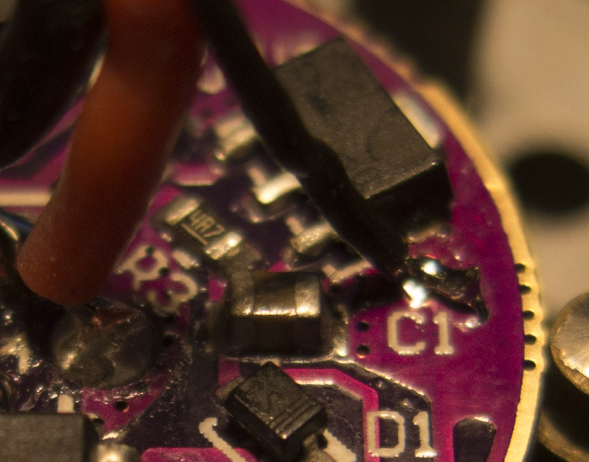
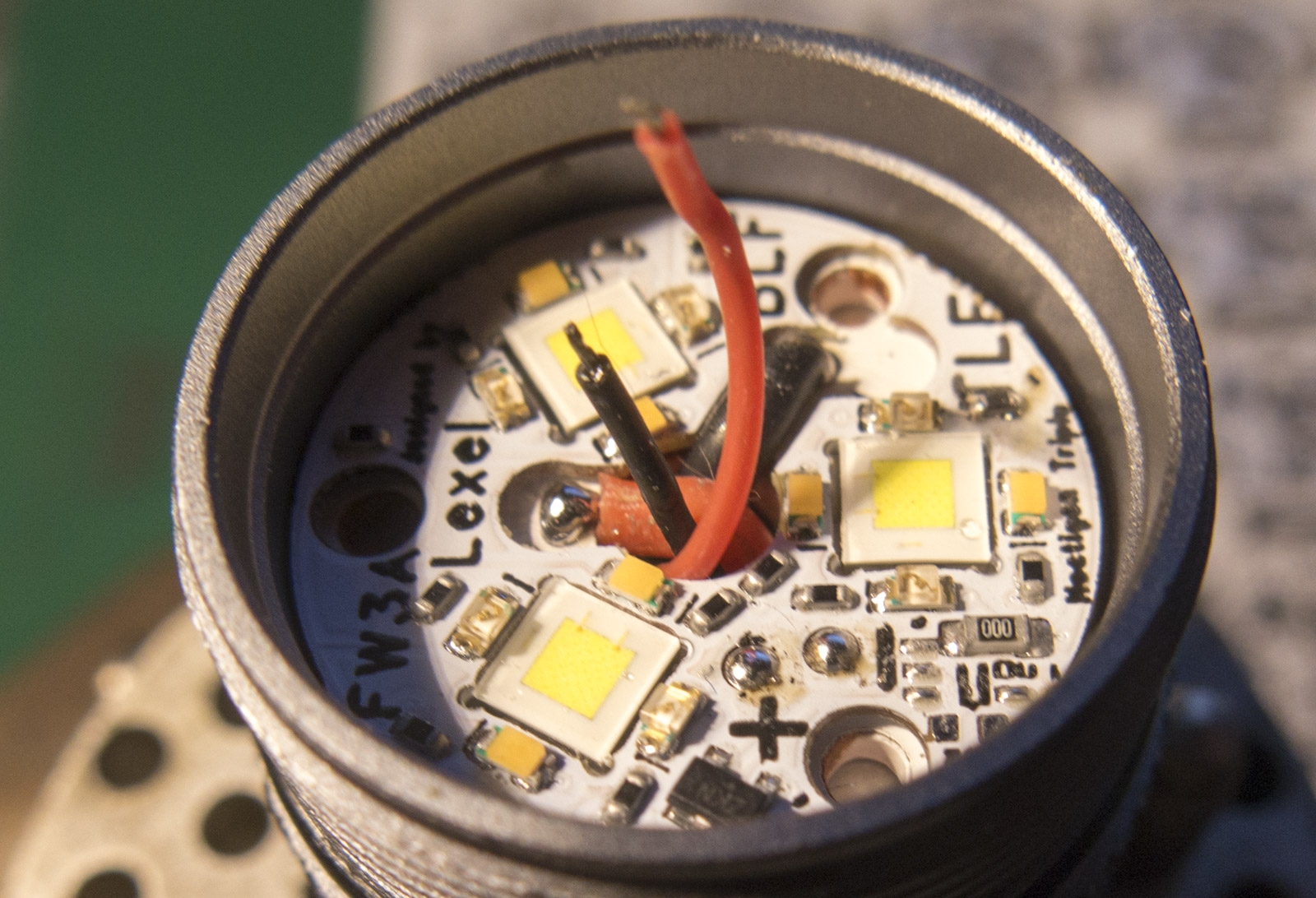
Remove the optical nerve resistor and tin the right pad

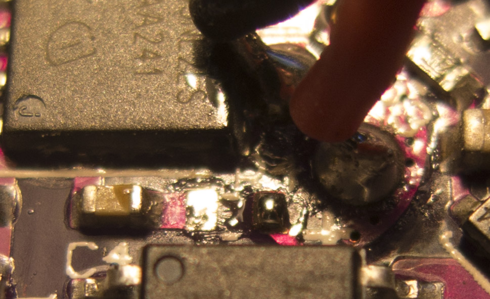
Prepare a thin wire for the aux board + connection and solder it to the tinned pad

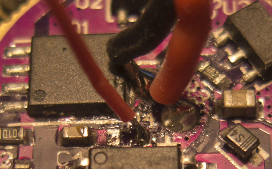
(AWG28 silicone wire used, it’s cut a bit too long)
Scrape off some solder stop mask and tin the area for ground and solder the 2. wire to it
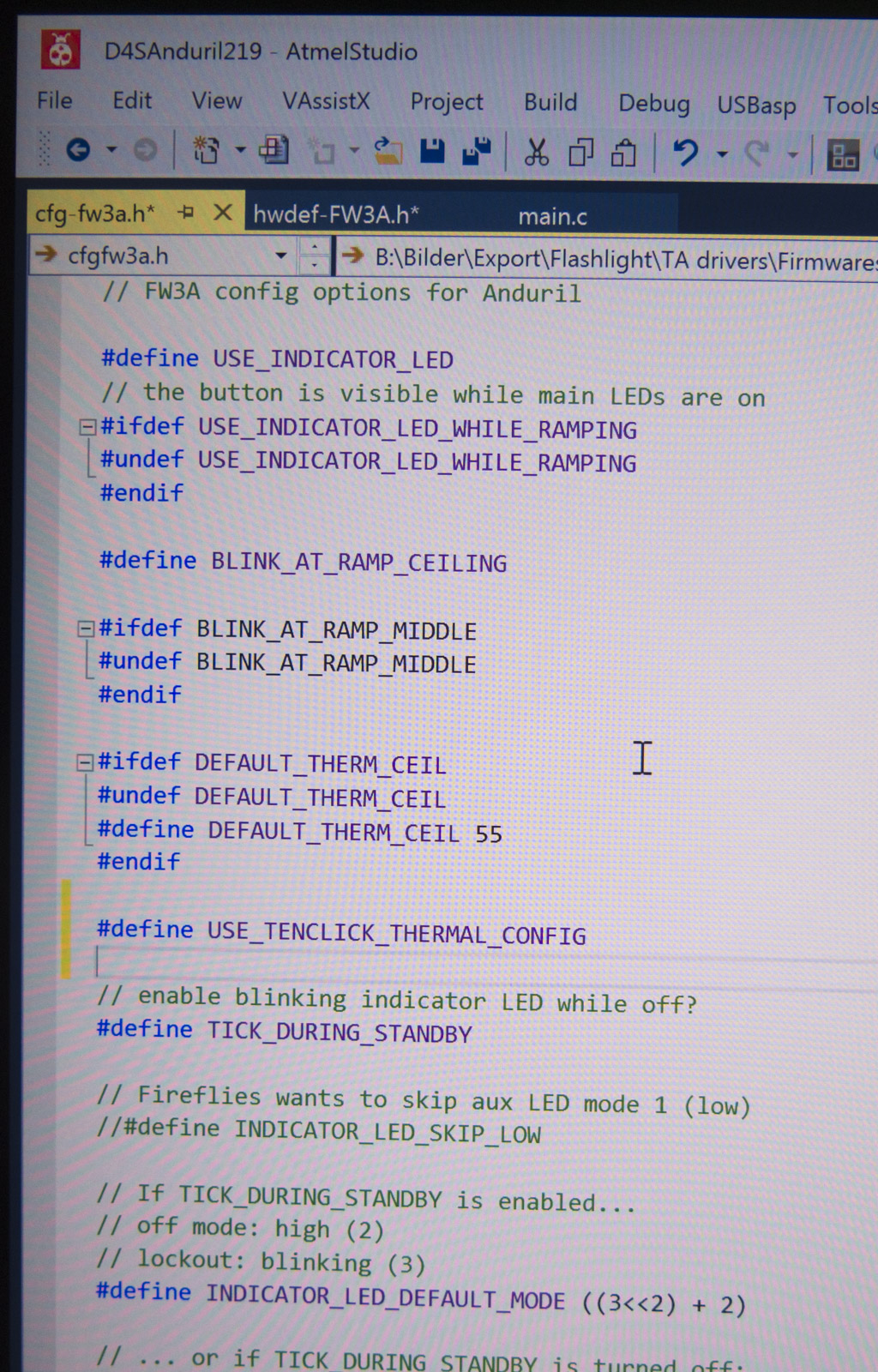
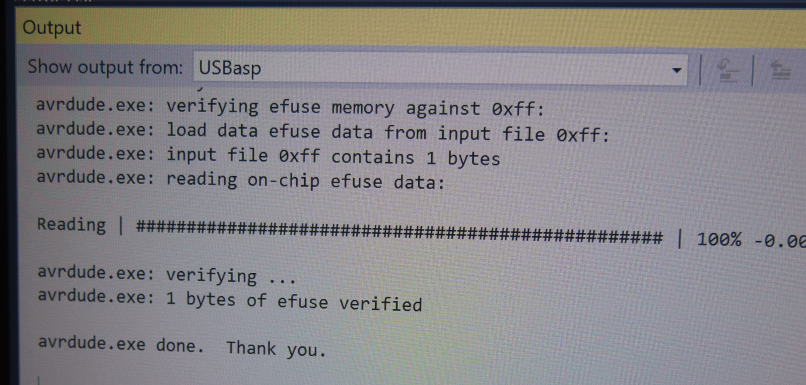
Modify Anduril for Aux support and flash MCU with programming adapter
It’s not stock Anduril there are some changes
http://www.metronixlaser.de/bilder/flashlight/FW3A/Anduril_aux.zip, its a bit old by now, there are newer projects in my how to flash topic here

Align the driver with the flat side to the head so it rests flat on the whole surface and screw down retaining ring, solder MCPCB


Pad soldering
Hardware
- 295°C Weller WSD81
- Felder 0.5mm Sn62Pb36Ag2 with 3.5% flux (one with relative much rosin core flux, general use not SMD which has less flux %)
Preparations
- clean PCB with Alcohol and cotton swab
- twisting the wires end (helps to prevent splicing while soldering)
- cleaning tip in sponge
1.
- pre tinning pad and wire
- heating up pad and stick the wire end into it
- same as 1. just adding extra flux (for example if you use a SMD solder wire with only 1% flux)
- directly solder wire to the pad (not recommended but works fine with a solder wire with 2.5% or more flux)
in the video I look without any magnification to the soldering, just the camera records

.
Aux board is build and tested, put it on the MCPCB

solder the Aux pads + and -, add optic to the light then screw down bezel with lens
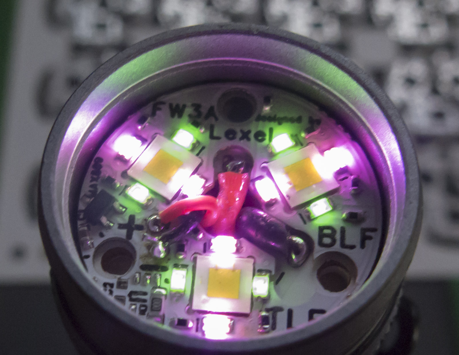

(The picture shows v1.5 with green/pink build for 1mA max current and a 0 Ohm resistor, higher value like 1-5k can make the board significant dimmer)