Hey all,
Finally getting around to posing these. I'm not sure if there are take apart threads on these lights yet or not, but I figured I would add mine to the bunch either way :)
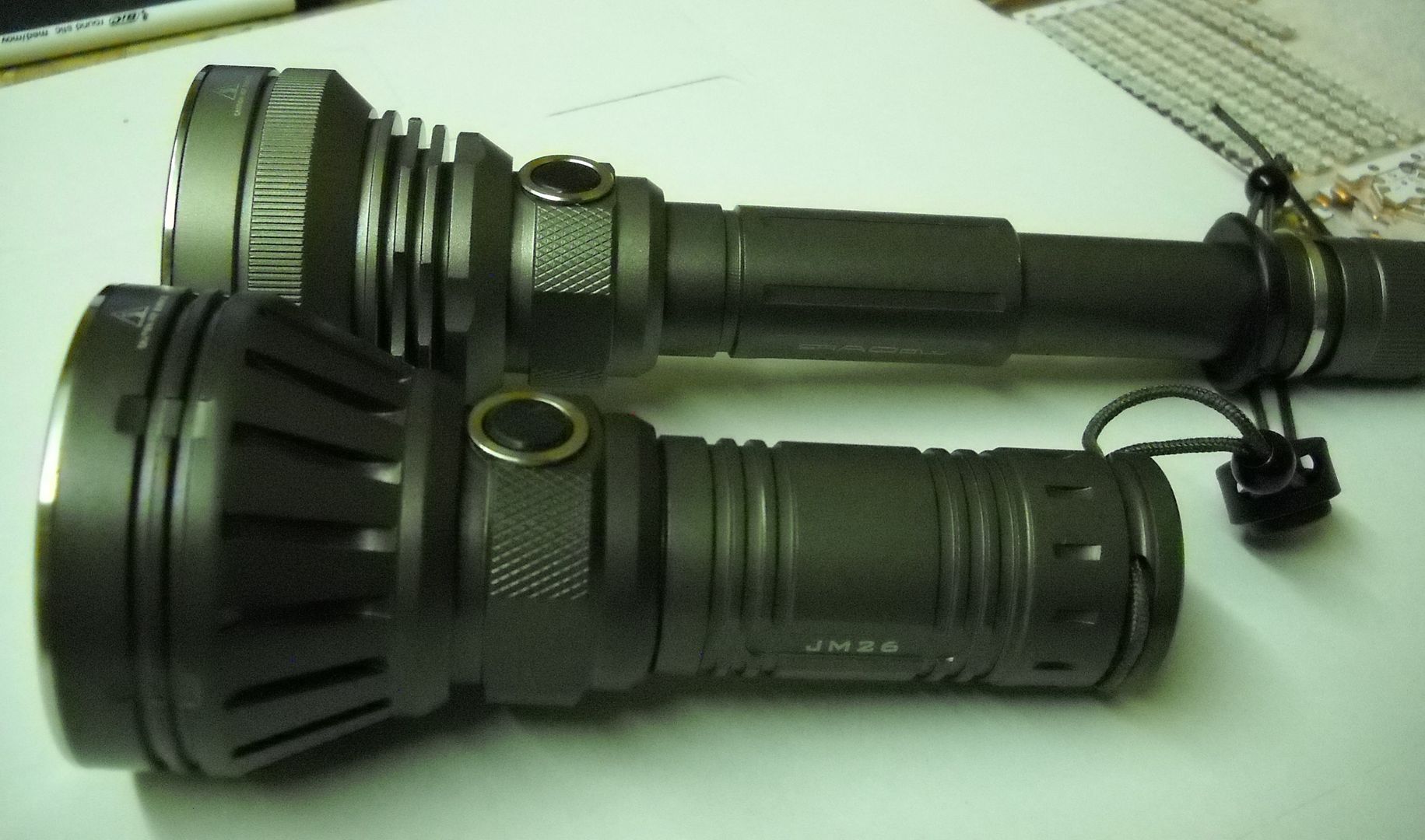
Let me start by saying, I really really like these hosts. They both feel like 150 dollar lights in your hand. The machining quality is impeccable. The reflector is amazing, and the over all design is good too. Beyond that the color of the bodies is almost like a surefire which happens to be one of my personal favorite.
Anyway all that said there is still much room for improvement with the output and especially the user interface.
The JM26 is a straight e switch and the TC 500 is a dual. IIRC the factor UI for the 26 was like press and hold for on. Additional clicks got you h,m,l and 2 fast would give strobe. No memory always starting on high.
The TC 500 was the same accept for the tail switch lock out, but even then you always got high when you turned it on :(
The emitters were first gen cree XML.
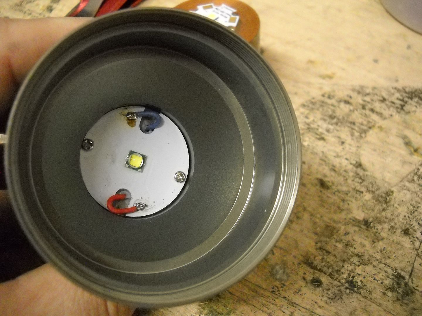
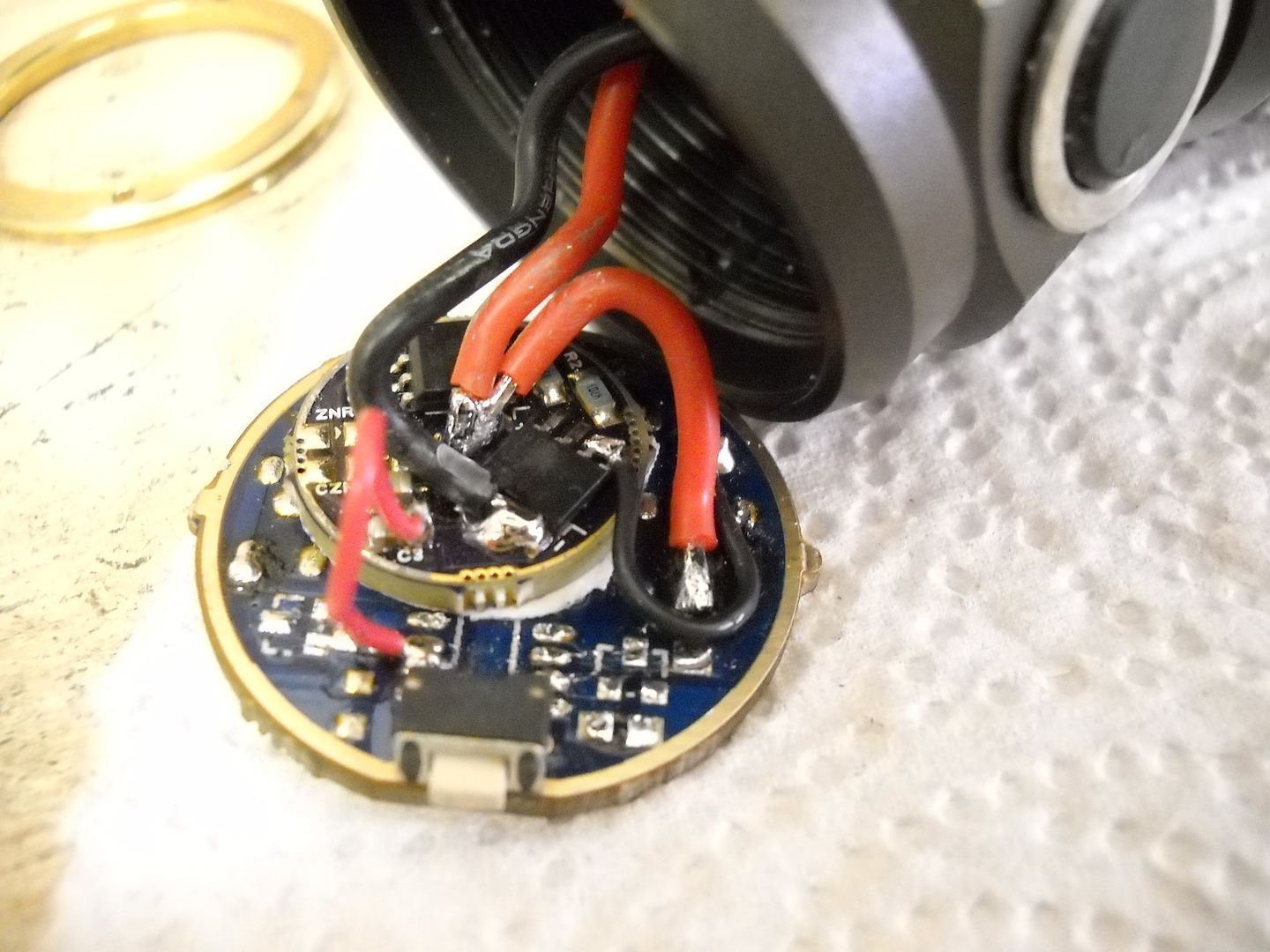
These lights are simple to get apart. The bezels unscrew and are not epoxied, and there is a retaining ring that holds the drivers in.
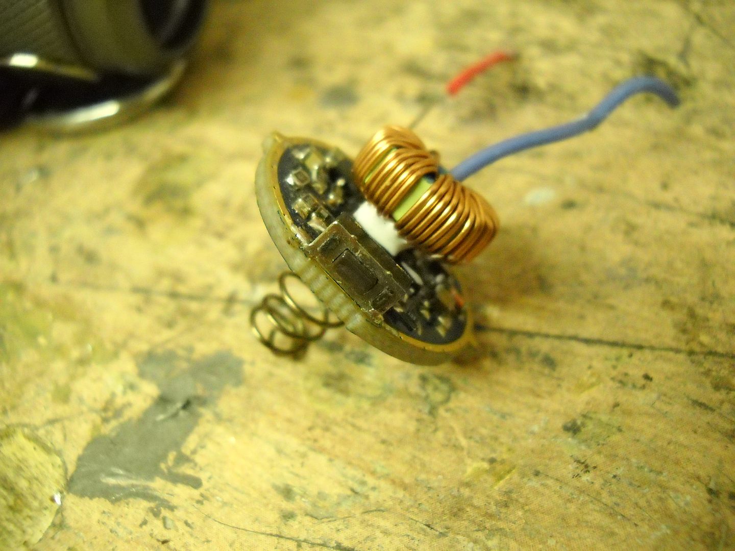
The TC 500 has a spring and a buck driver with a large inductor on the top. The JM26 does not have a spring. Its driver is a 7135 based driver similar to a nanjg105C
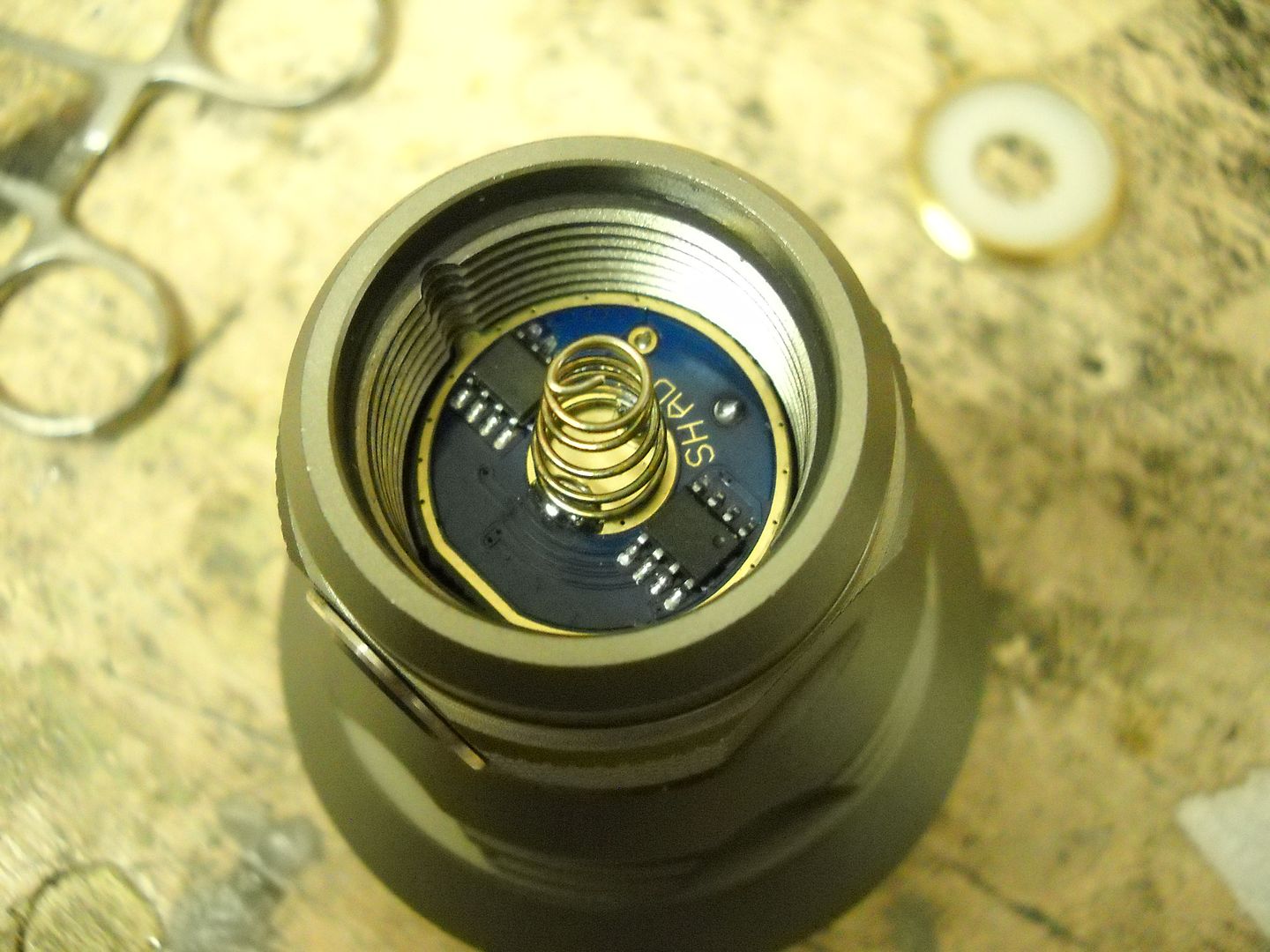
The switch is actually attached right to the PCB on both models. I kept that and removed all the other components on the both.
The JM26 had a flat peice of plastic with a brass nipple which is counter sunk into the pastic for a revers polarity protection. This means 26650s do not make contact at the + end :( While I had them apart I removed some material from that one.
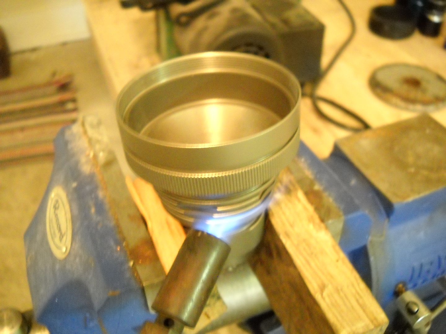
In the top end we find a Maxtoch 32mm aluminum board.
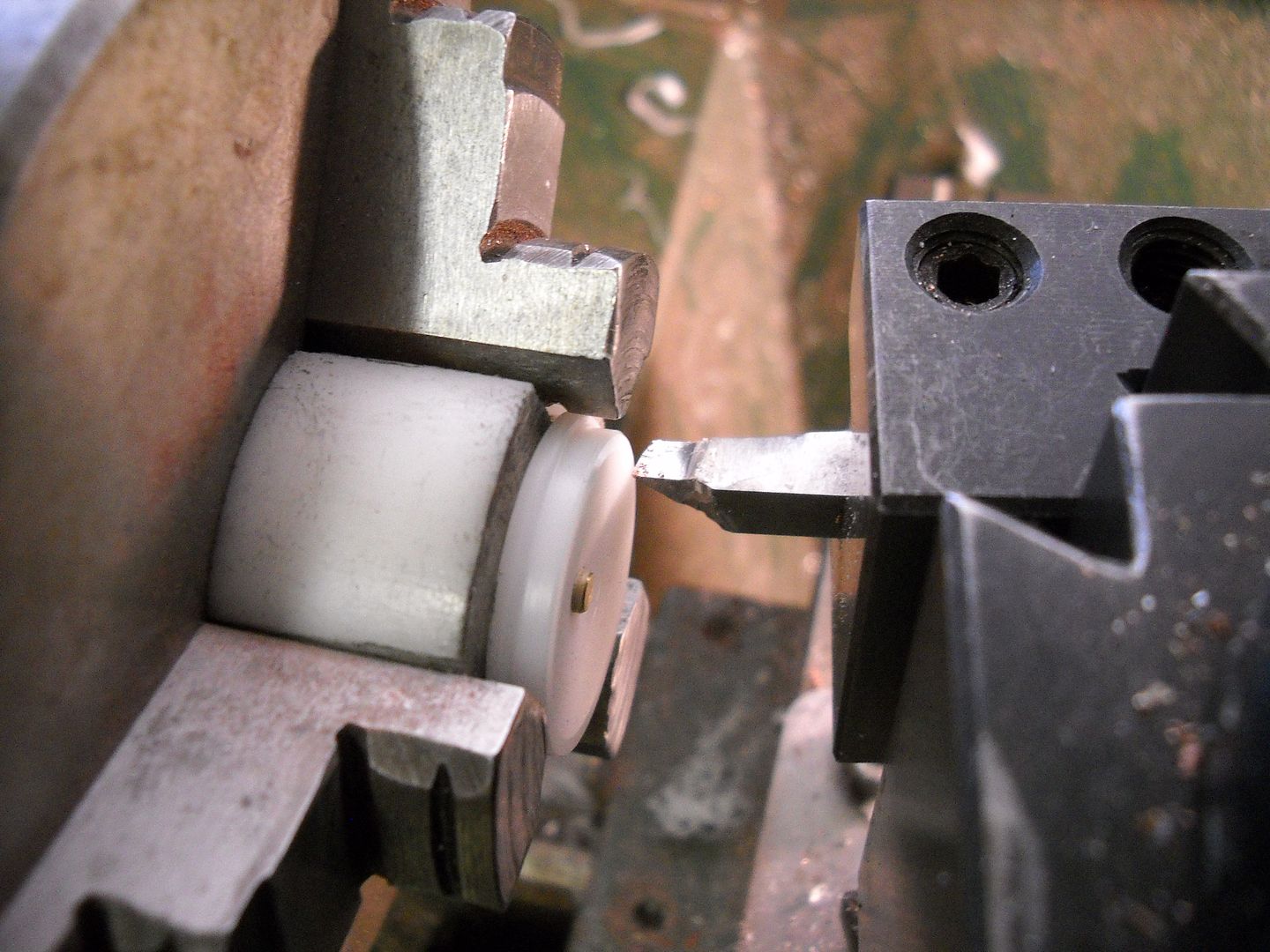
Even though there are set screws the board was still glued down so in order to remove it without harming the metal surface I enlisted some help.
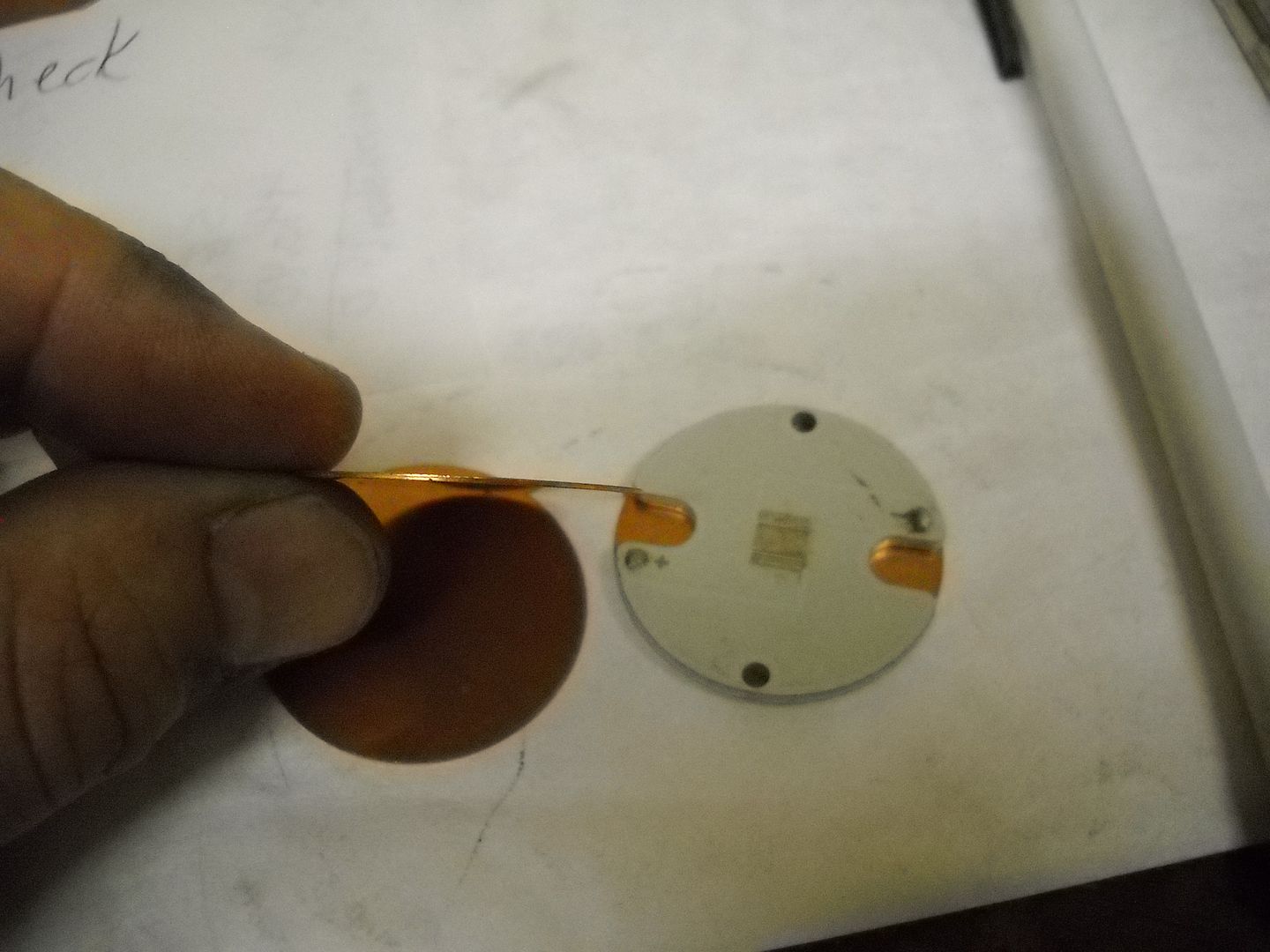
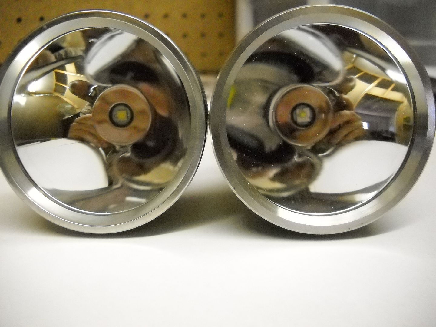
With that done I installed a copper 32mm board with a de-domed XML2 U4 in the JM26. For some reason the copper boards are not as thick as the aluminum ones, and in this case it effected the focus. The reflector would not sit down on the centering ring so I reflowed the mcpcb to a 32mm copper disc I had.
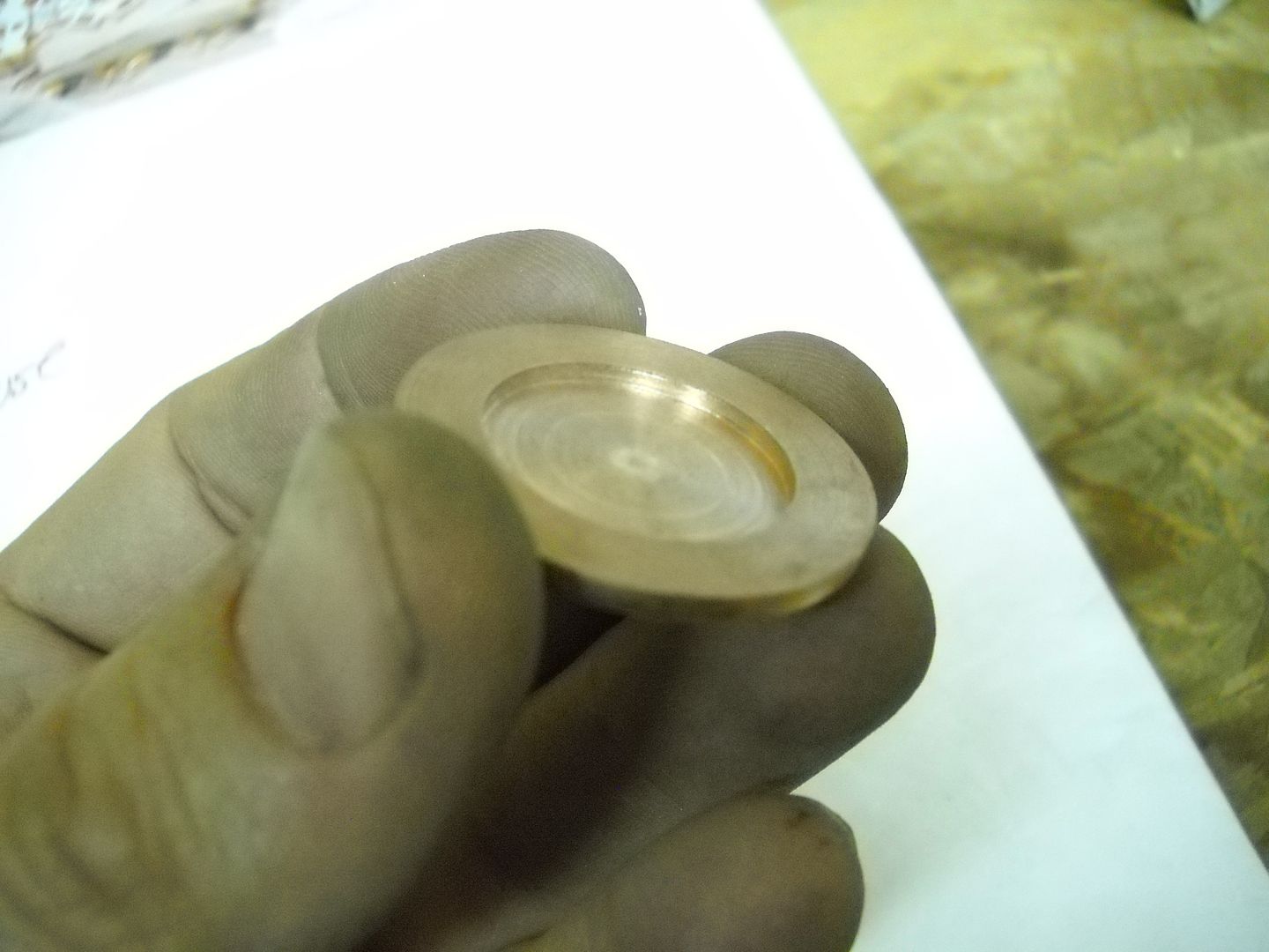
For the TC 500 I used the new Cree XHP-35 C4 HI. I did not have a 32mm mcpcb with an XPG foot print so I use a 20mm SinkPad and machined a spacer with a bottom plate on it the appropriate thickness ( about .020 IIRC)
I removed all the components from both of the factory drivers accept the switch and installed a mosfet driver for each.
The UI for the JM26 is Tom_Es e-switch version of the Star Code which is a favorite of mine. I extended the window for changing the modes on start up and the output values but that is about it. Its now a 5 mode that defaults to low, but has instant access to high and strobe as well. 1 click on, one click off.
The TC500 has Jonny Cs dual switch firmware. 5 mode, and the tail switch for a lock out. Comes on in what ever mode it was left in.
All back together now.
Both lights were used in some extensive tests in the XHP-35 thread which I will not fully repost here.
https://budgetlightforum.com/t/-/34614?page=2#comment-801290
Test results on fresh batteries at one minute runtime
JM26 1326 lumens, 238,500 lux, 4.6amp
TC 500 1616 lumens, 203,750 lux, 2.6 amps
The beam from these superb reflectors is very nice. The hot spots are both very round and smooth. There is a tiny bit more "fuzz" around the hot spots in real life, but this picture is close.
Left is TC500
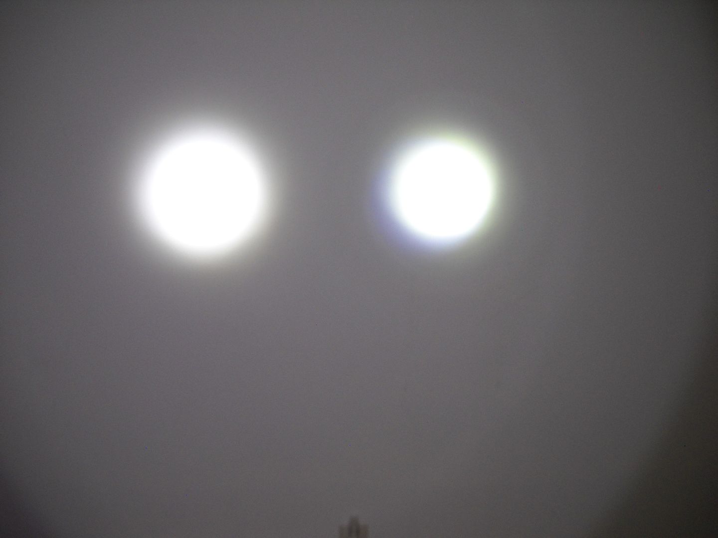
So they are both fairly similar. The XML2 gives more lux, but the XHP-35 delivers more lumens. The beam on the XML2 is more lazer like because the spill with the 35 is much brighter.
EDIT:
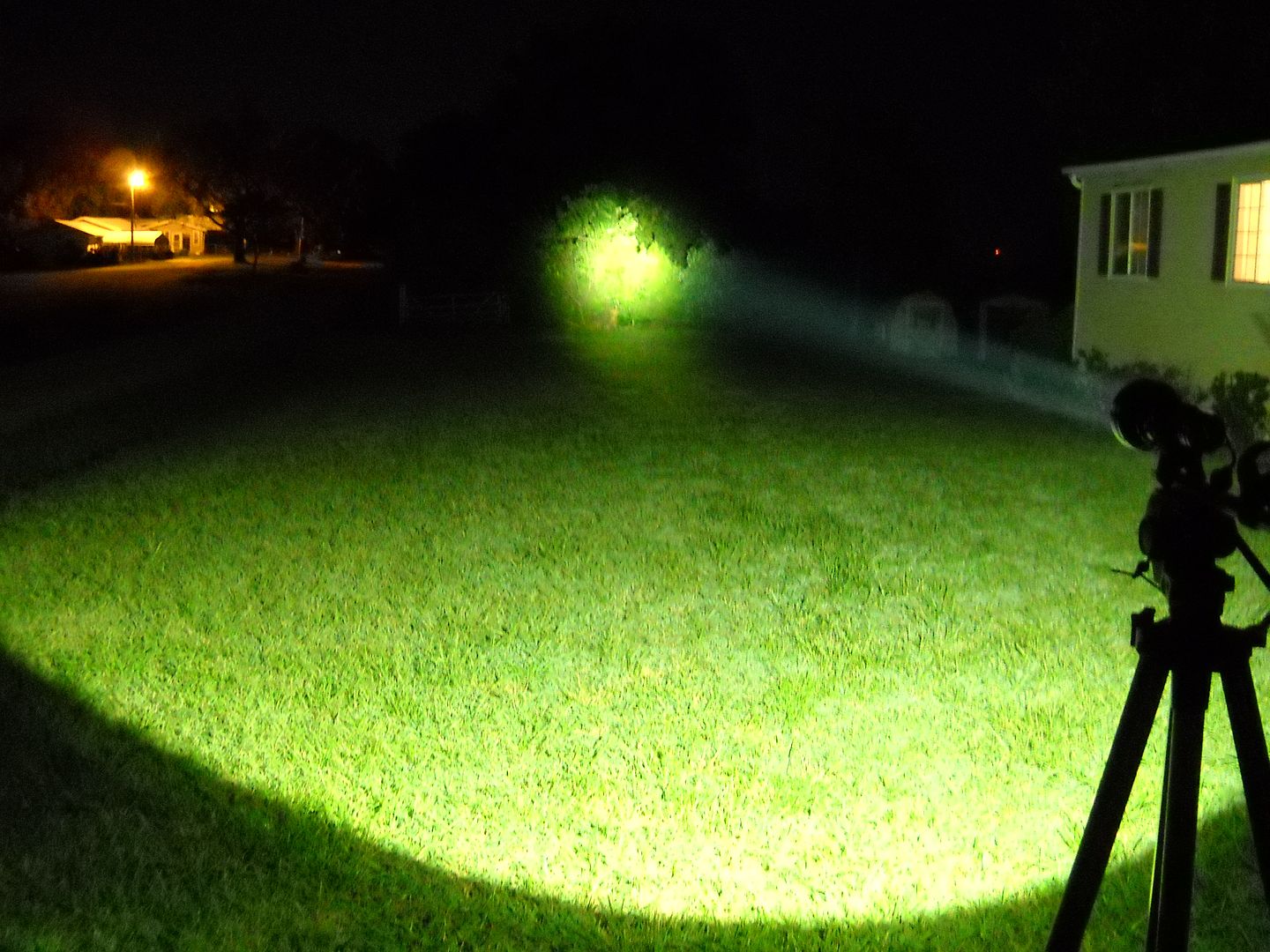
Beam shots.
JM26
TC500
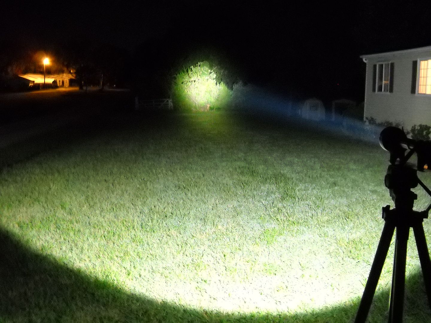
Now farther out. Those trees are about 400 feet IIRC.
JM26
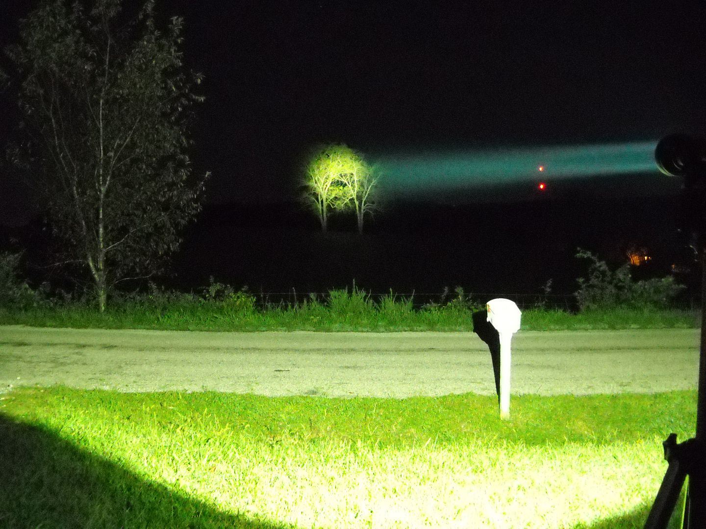
TC500

Hope you all enjoyed 