This won’t be a big thread as it essentially just an assembley but I thought I would just document the build up of my new Sinner Ti-XC which arrived this afternoon!
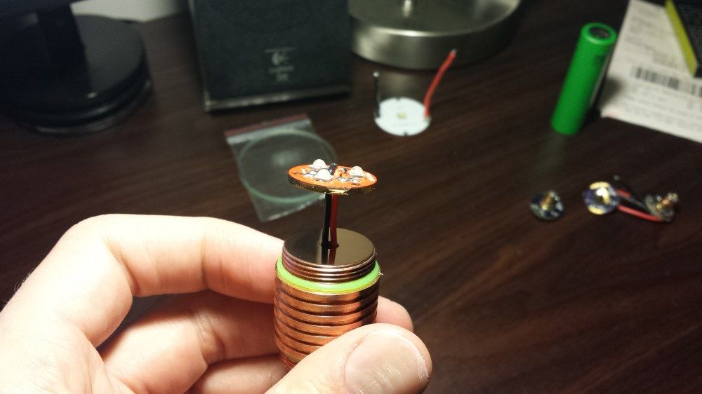
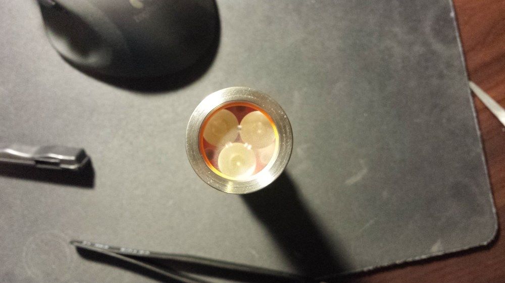
I will be using a BLF17DD driver and a 3XP Noctigon with XP-G2 R5 5A2 emitters. Not sure which Carclo optic to go with yet but I have the full set ready to try.
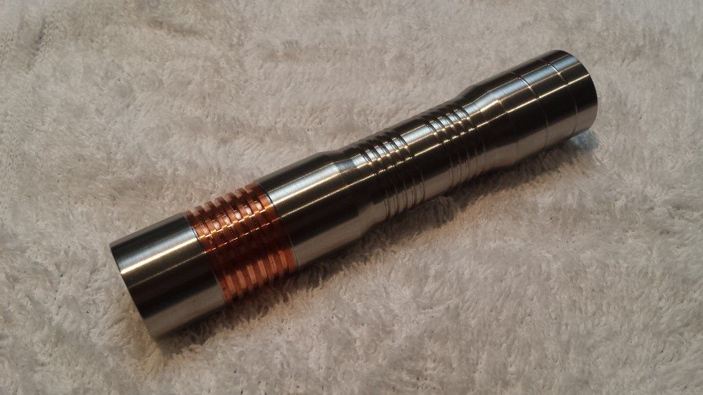
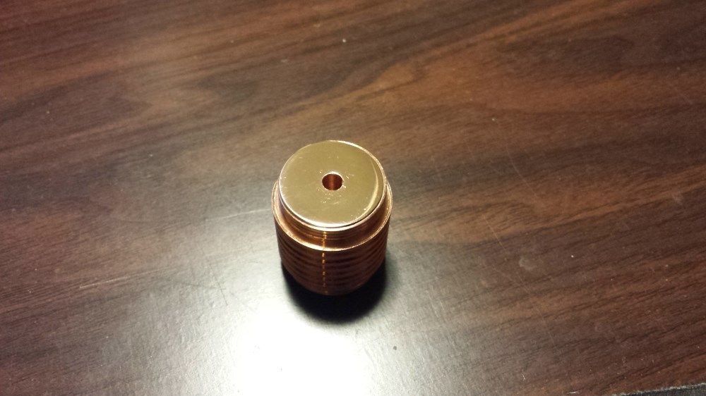
First up the host which I am absolutely stoked with!
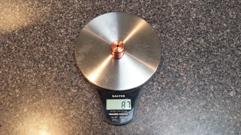
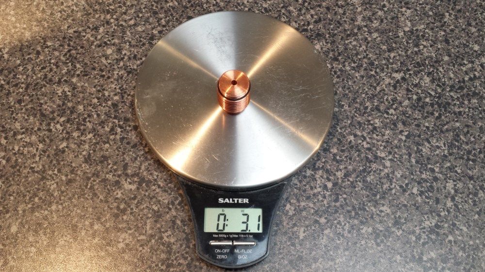
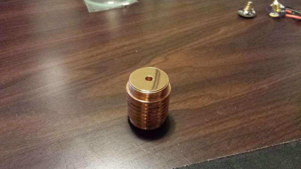
A nice 87g chunk of copper which the star will be mounted on…
or ~3.1 Ounces for those of you playing in America
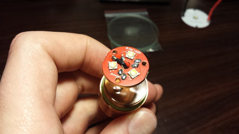
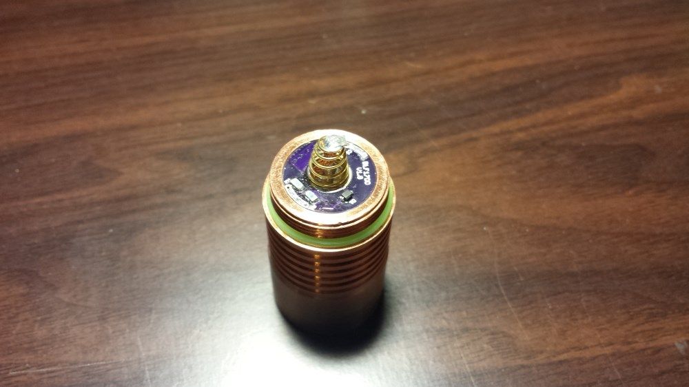
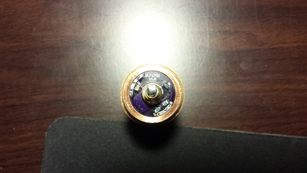
So the build is pretty much finished. I first of all sanded both the face of the star and the face of the pill with 1200 > 2000 > 3000 grit sandpaper and then polished it with some Autosol metal polish. I then followed that with some isopropyl alcohol to remove any residue of the polish. I then replaced the stock 22awg silicone wires which are pre-installed with some 20awg teflon silver plated wire. I added some Arctic Silver 5 thermal paste and twisted the star around to ensure a nice thin even coating between both surfaces. I then screwed the head together with a Carclo 10508 optic. The orange o ring which is supplied with the host is a little thick and protrudes into the opening a bit so I will look at buying a thinner one. Next I installed the BLF17DD driver. I had to just lightly sand the edges to get it to fit snug but so it could still be removed if it needed to be. I put some copper braid in the edge of the driver recess and then pressed the driver into it and soldered the top of the braid to the earth ring. This ensured I had a good earth to the body. All modes are working and I’m very happy with it!
The only issue I have is, with a fresh VTC5 it is only pulling about 4A on high which is no where near what I was expecting for a 3 x XP-G2 setup and a BLF17DD with some high quality 20awg wires. Any ideas why it is only pulling such little current? I thought perhaps the titanium body was hindering it as titanium isn’t a very good conductor of electricity??
Did you test (and measure tailcap current) the driver, plus star (and emitters) outside the light, with the same battery, to compare?
Also, did you try a different battery?
EDIT: What type of meter leads are you using when measuring tailcap? A long pair of thin lead wires will definitely cause lower tailcap current measurements in my experience.
Nope, unfortunately I only tested the set up once installed in the light. I don’t really want to pull it all apart now because it is never as clean and nice after it has all been pulled out and re-done.
I have also tried a brand new Samsung 25R with similar results.
Also, I forgot to mention that was a tailcap current reading I mentioned previously.
Good god man, what is the wood like surface on which you’re working? Where’s your assorted bit’s of wire and random components and flux residue and tools and random batteries and drivers and lights in different states of assembly?!
As for why you’re only getting 4A, thats very strange, I get >10A to those triple’s on a 25R with 22AWG, the only thing that stands out as different from your build to mine are the solder jumpers you used, what kind of solder? The first thing I would check is that each individual emitter can support full draw, remove the jumpers and apply power directly to each one with an ammeter / DMM in line to measure. I’ve gotten XP-G2’s that are bad and will only draw ~1A out of the tape.
hahaha my workbench doubles as my computer desk so I clean everything up once I have finished working on things for the night. All the parts from partially completed lights are in their own containers so I don’t mix up parts and all the left over drivers, emitters etc etc are neatly organised in divided storage containers. I am a bit of a neat freak so everything has its own place! haha
I was expecting around 10A because I had read about many people on here getting similar results including yourself. I use 63/37 solder and haven’t had any issues before with low current draw? Thanks for the suggestion, I will try what you have mentioned and see how I get on. Although I won’t get it done now tonight so will have to report back later.
haha I had no idea what that screw was for! but it makes perfect sense now! I would have thought the way I have the earth setup would still be a pretty good connection?
If I connect a battery directly to the driver spring and ground ring and take a reading that should rule out an earth issue shouldn’t it?
Ok, some improvements have been found but I’m still not there. Turns out I picked up the slightly used VTC5 and not the one I had checked the voltage of (stupid me!!). Anyway now with the definite 4.20V VTC5 I am getting 6.80A at the tailcap. So it’s an improvement but still not the 10A I was hoping for.
Comfy recommends it as being a wee bit tighter than a 10507. I’ve got 3 up XP-L’s de-domed under mine. It was “only” pulling 10.7A so I’m redoing it this morning. I too bypassed the ground screw and I think it’s pretty tough getting a solid ground on that big copper pill with solder. At any rate, the solder came off all too quick and clean so I’m pretty sure I’ll see more amperage and output with the ground screw utilized.
Damaged the driver getting it out, building a new one. Hoping to see more than the 3126 lumens I was seeing.
Ah that’s interesting, I hadn’t thought of polishing a frosted one. Do you recommend anything in particular to polish them?
I also found that the solder wouldn’t stick to the copper so I sat a piece of copper braid in the edge of the opening and then pressed the driver into position and it took a bit of pressure so the braid will be making good contact with the pill. I then soldered the exposed braid to the driver. I’m pretty confident I got a good earth doing it this way.