This flashlight is not new, but it’s still on sale. I bought one, but unfortunately it has arrived dead – most of the time it would blink red, and only sometimes it would turn on. This hinted to contact issues somewhere, so I’ve decided to take a look inside. Let’s go!
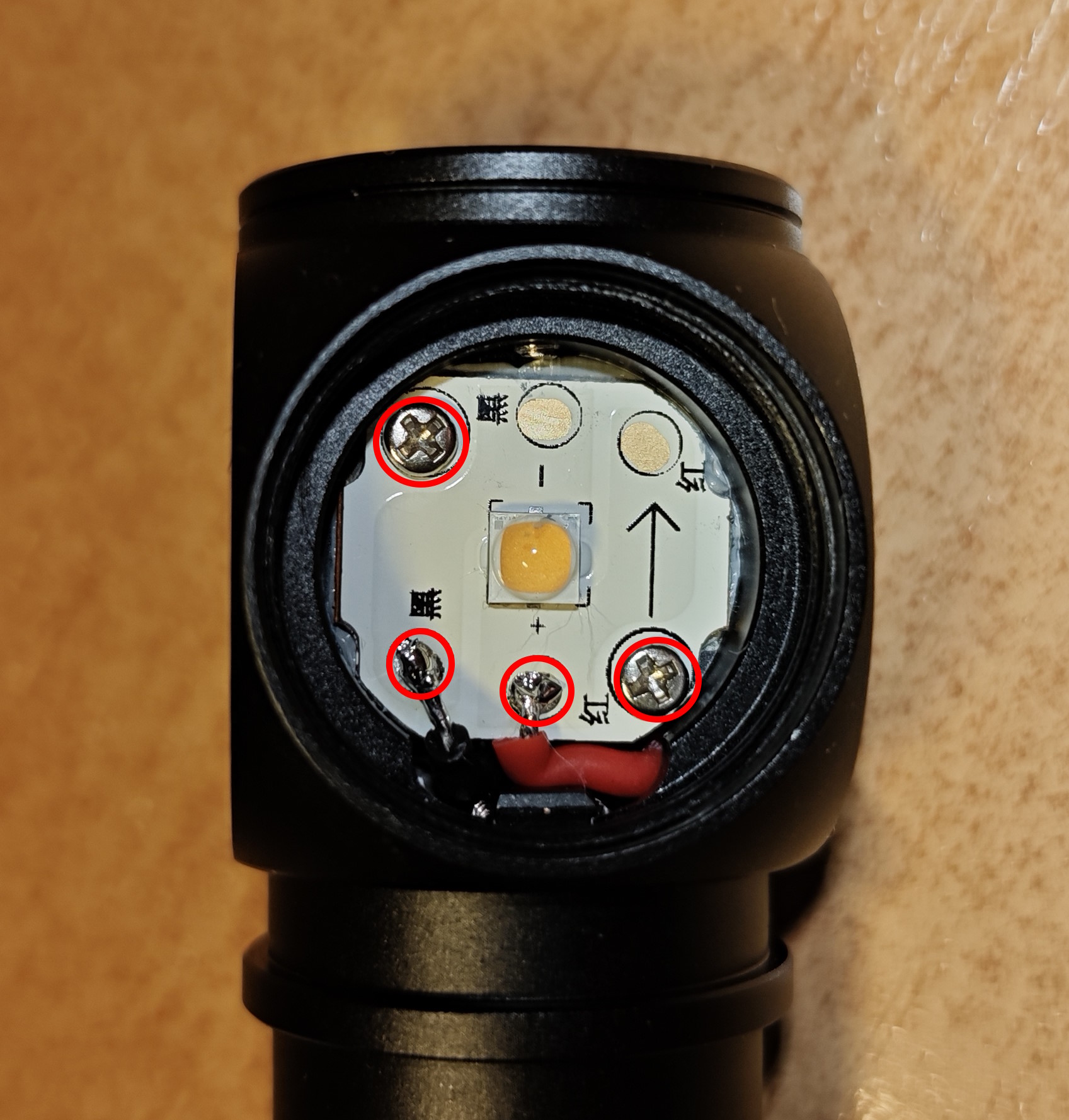
The first step is to unscrew the button bezel. Press it against a piece of rubber (the backside of a mouse pad should work). Once done, you’ll see the upper PCB:

You need to undo the only screw and de-solder the four solder joints – use desoldering wick to wipe the solder away.
The next step is to remove the LED MCPCB. Unscrew the emitter bezel (again, using some piece of rubber):
Remove the screws, lift the MCPCB and desolder the two wires.
Once done, the remaining PCBs can be pushed down the battery tube: the tube is hollow, and the boards aren’t being held by anything else. Here is a view from the bottom of the tube:

Here are all the electronic parts:

Here are some additional photos of the driver:


None of the solder joints looked bad from the outside, but I’ve redone them all anyway, and my contact issues have vanished away.
To assemble the flashlight, do all the steps in reverse. One you get to re-soldering the button PCB, I recommend doing it with battery inserted and USB cable attached – this way, you’ll solder the boards in their most natural position, introducing less stress to the joints.
Now, some closing thoughts: the design of this flashlight could have been better. The only thing that holds the driver in place are the solder joints. But solder is a brittle material, it must never experience mechanical stress. And yet, in this design, solder joints are load bearing – every time you rattle the battery or insert your USB cable, you introduce some tension to the joints. This is how failure by design looks like.
My hypothesis is that the flashlight was fine straight from the factory, but the horrors of international shipping with battery rattling inside have introduced enough stress to make an internal crack somewhere in the solder joints.
The joints on the button PCB seem to bear the most of the load, so if you encounter similar issues, my recommendation is to re-solder them first. But you may also have to disassemble everything and redo the other joints as well.
