Swapped in a Nichia 519A on the first host and it works fine on lower brightness settings, but when I go turbo or ramp up to the highest level, the light steps down or turns off after a few seconds.
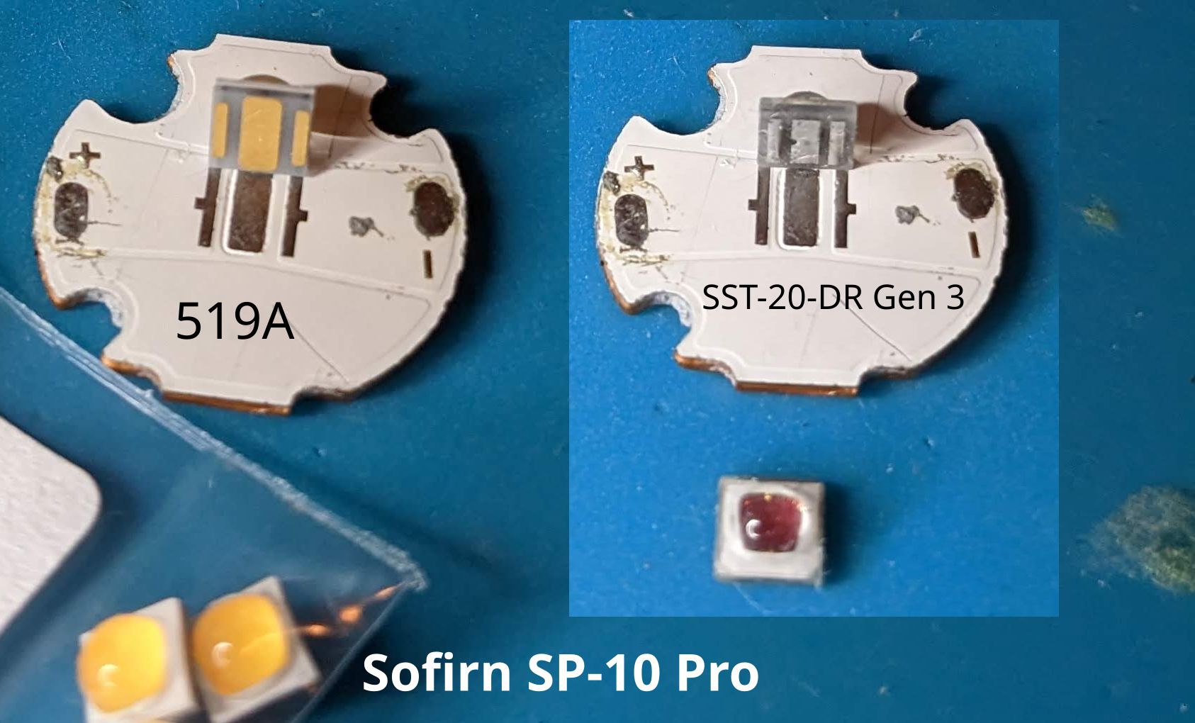
For the second host I installed a SST-20 Deep Red 660nm, yet the LED doesn’t turn on at all. The factory LH351D has the same footprint (3535) as the 519A and SST-20, so I’m guessing they should work.
Do I need to somehow modify each light’s anduril2 configuration to support these new emitters? Also, the diode setting on my multimeter doesn’t light up any LEDs I tried - is there another method to test? I really like this light so I’ve got more hosts and LEDs to try.
Did you reflow it onto the MCPCB? It’s possible it has a bad connection.
You could try using a low-current batteries, like 3s (alkaline) AAA, but I’m not entirely sure what current it’ll run at. Might be a good idea to use mostly-depleted ones.
Maximum Vf is very low on the Gen 3 sheet and still under 3volts on the other
Could it have been hit by too high a voltage and burned out instantly with no flash or anything? I dunno.
.
.
Not sure about about the 519A issue as I have not got around to swapping the emitter in mine for a 519A. However, I think that swap has been done successfully already, but not positive about that. That does sound a little like the cell not being able to supply sufficient voltage or current
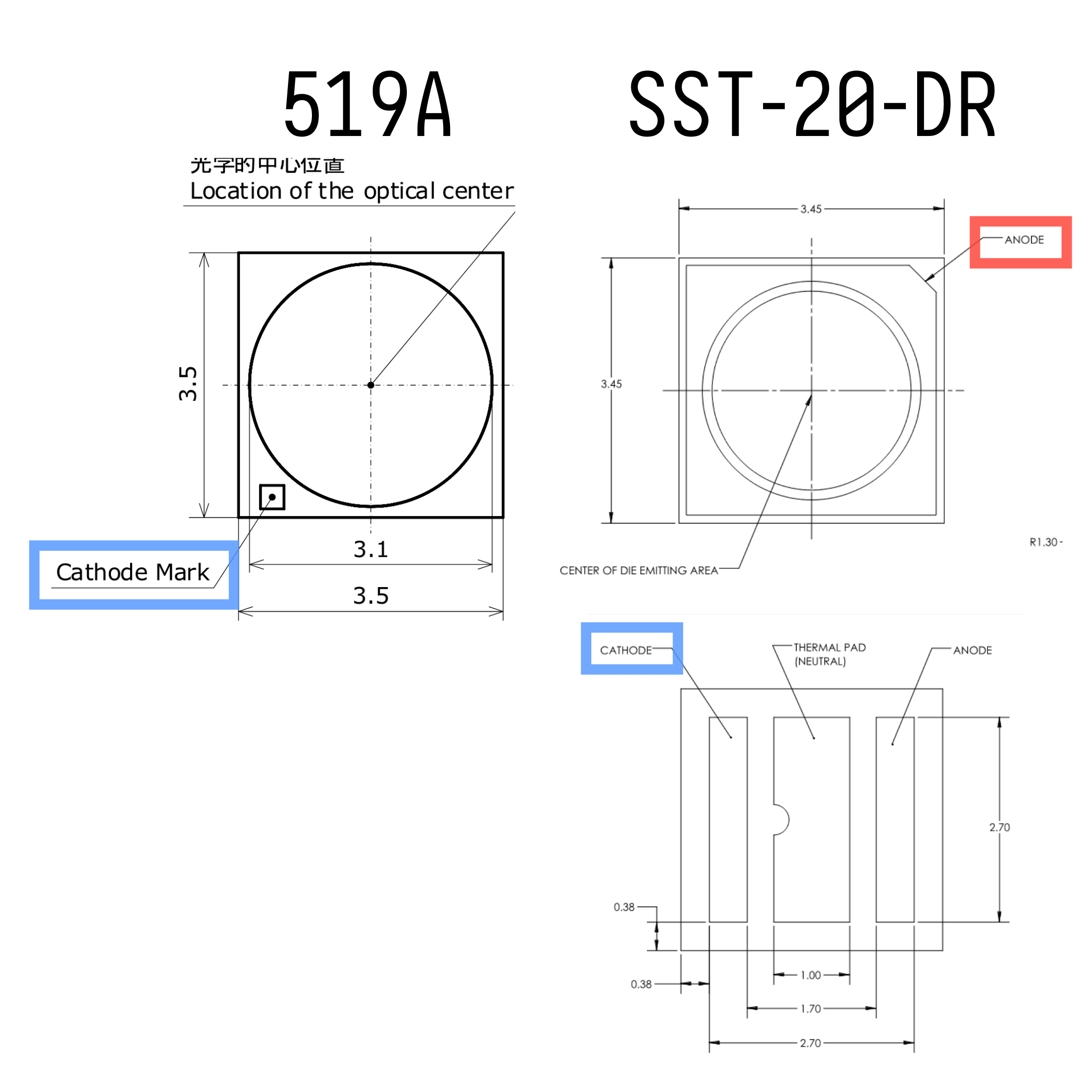
The SST20 deep red has 1) much lower Vf and 2) different footprint (3030 actually despite the 3535 size), so the existing driver/board would not work.
Not sure what’s going on with the 519A, it has a lower Vf than the LH351D so it’s possible it’s trying to draw more current than the cell/driver could safely provide.
On the 519A light, I tried all my available fuels and narrowed down the problem to my Acebeam USB-C rechargables. My other 14500 and AA batteries work much better and step down gradually as the light heats up. Stock LED seems to maintain brightness for longer, but oh well. Solved!
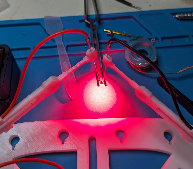
For the Deep Red SST-20, I verified it is Gen 3 per the data sheet linked above. Luckily I bought two red LEDs in case I donked it up. I pulled the PCB from a second host and applied 1.1A @ 2.6V to the solder pads before removing the LH351D and it lit right up! Armed with a way to verify my reflow connection, I decided to attempt the process on the SST-20 again with my extra host and LED. The operation seemed to go smoothly, but no illumination when I apply 700mAh @ 2.1V to the pads.
Perhaps I’m applying too much heat and cooking the LED during reflow? I did leave the PCB on the hotplate until it reached 210C, which does appear to be in conflict with the datasheet… Or QReciprocity42 is spot on and I just matched up the 3535 footprint hoping it would work… I wish I knew how this person pulled it off though: NLD/NED Sofirn SP10 Pro SST-20 Deep Ded 660nm
According to the datasheets the outside to outside measurement of the +/- pads on the SST-20 DR is 2.7mm and on a typical 3535 (nichia519) it is 3.2mm. Maybe it is possible with a precisely “just right” placement of the SST-20 DRemitter, to just make contact with both + & -. I dunno.
Seems like that could’ve been the problem, or maybe you used too much solder paste making the pads bridge. I doubt it burned out from excess voltage, but it’s always a good idea to start testing by ramping from moonlight, just in case.
If you plan to do more reflows it really helps to have either an external power supply or a multimeter with a diode check function. This will allow you to see that the reflow connected properly and also that the LED didn’t short to the thermal path. This beats resoldering it in the light and then realizing you have a problem.
Before I got an adjustable voltage and current power supply I used a makeshift LED test power supply by taping two wires to the + & - sides of a CR2032 cell. 3 volts and limited ability to supply much current allowed momentary application of power to a newly reflowed mcpcb with LED.
I tried to reflow again, but no luck so I pulled both from the PCBs.
This feels like a real RTFM learning experience for me. I just got into flashlights a few months ago and thought I could match up the 3535 footprints together and be on my way.
I do have a power supply with adjustable voltage and current. I connected some needle probes and applied 1.1A @ 2.6V directly to the known-good LH351D I pulled and it works. But when I do the same operation to both raw SST-20-DR with 700mA @ 2.1V, nothing happens.
So either I managed to connect to the pads during reflow and fried the LEDs from overvoltage, or I cooked the LEDs too much during reflow, or something else? Either way it looks like I need to sit down with some data sheets and order some more LEDs.
Can’t remember exactly what MCPCB diameter the SP10 Pro uses (regular SP10 is 14mm), but you could order a 3030 mcpcb and some more red SST20 from convoy.
AFAIK they’re only available down to 16mm normally, but Simon might have a smaller one, and if not it can probably be trimmed down (carefully, so as to not short the surface traces to thermal on the edges).
The 519A has the cathode marked – the SST-20-DR on the other hand has the anode marked on the top of the LED and the cathode side notched on the bottom. Guess how I realized that…
3030 footprint LEDs can be reflowed on 3535 PCBs. It is more difficult, as the surface tension of the solder can easily pull the LED off to the side if slightly perturbed, losing electrical connection. But it can be pushed back to center with some gentle tweezers taps.
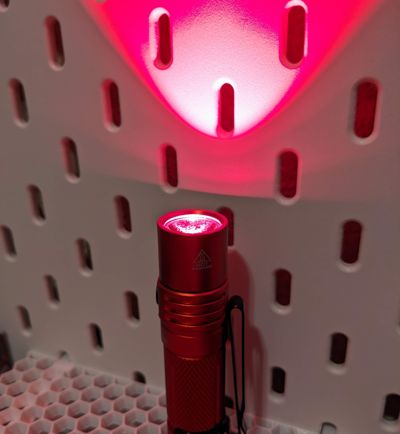
Agreed, I installed the 519A first and it worked immediately. I just included the side-by-side pics of both emitters lined up with the PCB pads for a comparison. Working vs not working
When you put the lights back together make sure the solder blobs do not hang off the board or touch the underside of the reflector. I learned that lesson the hard way.
Some lights don’t have much clearance so a layer of tape (electical, kapton, etc) on the reflector is good insurance. It’s also critical to use a gasket on the reflector to prevent shorts.
After every reflow, I do a few checks before installing the star back into a light.
Specifically, I do the following:
Check for shorts using pocket DMM - I place a probe on the + wire solder point on the star and a second probe on the base to check for a short. I repeat this test with the - solder point, and again between both the + and - points.
Check for too much or not enough solder - I use a small magnifying glass (actually a leftover aspheric lens) to examine all edges of the led where it meets the star. Specifically, I’m looking for raised edges due to too much solder or a visible crack due to not enough solder. It is very important that the entire heat sink pad has good connection to the star.
Check for function - I have an old low-power 14500 battery in a battery carrier with 2 wires coming off each end. I briefly touch these wires to the wire bondpads on the star to make sure all leds light up properly and are installed in the correct direction.
If the star fails any of these tests, I redo the reflow. Since I started doing these tests I have gotten much better results with all my reflows.
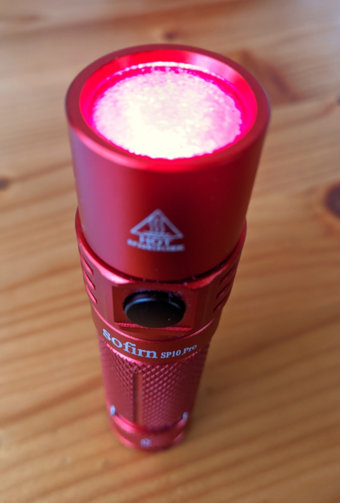
Both dedomed 519A and SST-20-DR look awesome. I think the SP10 Pro is my favorite light, I’m gonna search for more emitters that fit. Blue and green would be cool. Thanks for the help, everyone! I learned a lot here