Hammering the driver out with a pin through the switch hole appeared fruitless and only damaged the driver. So a new approach was needed, something drastic because the glue was tough. With the 80W beast I soldered a sizable strip of copper on top of the batt+ ring.
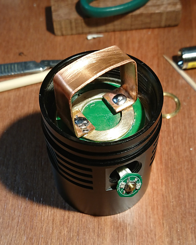
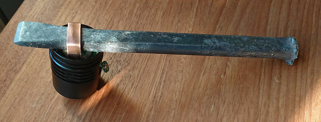
Chunk of iron was stuck through the loop, the head was placed on top of the partly opened vice, with the loop and chisel hanging loose in between. Holding the long end of the bar I started hammering carefully on the short end, each time a bit harder until the driver broke loose. (or the strip, or the batt+ring, luckily it was the driver  )
)
So here are some pics of what’s inside. As with the Q8 they used a nice copper board and the reflector is fixed in place with scews coming from the driver cavity, with the ledboard sandwiched in between reflector and shelf. The shelf is 5mm thick which is very adequate.
The reflector btw only clamps against the front lens, it makes no contact with the side of the bezel, there is a small gap to the side. But I can’t think of a problem in that.
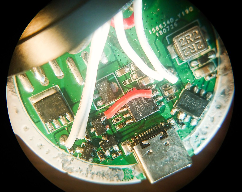
Mind that this is a prototype so some improvisation is expected, I see that the driver is hand-soldered, I see an extra cap soldered on top somewhere and a little jump wire, I see that they insulated the ledwires from the reflector with some led-centering thing (the concept of that is :+1: because it removes a potential risk).
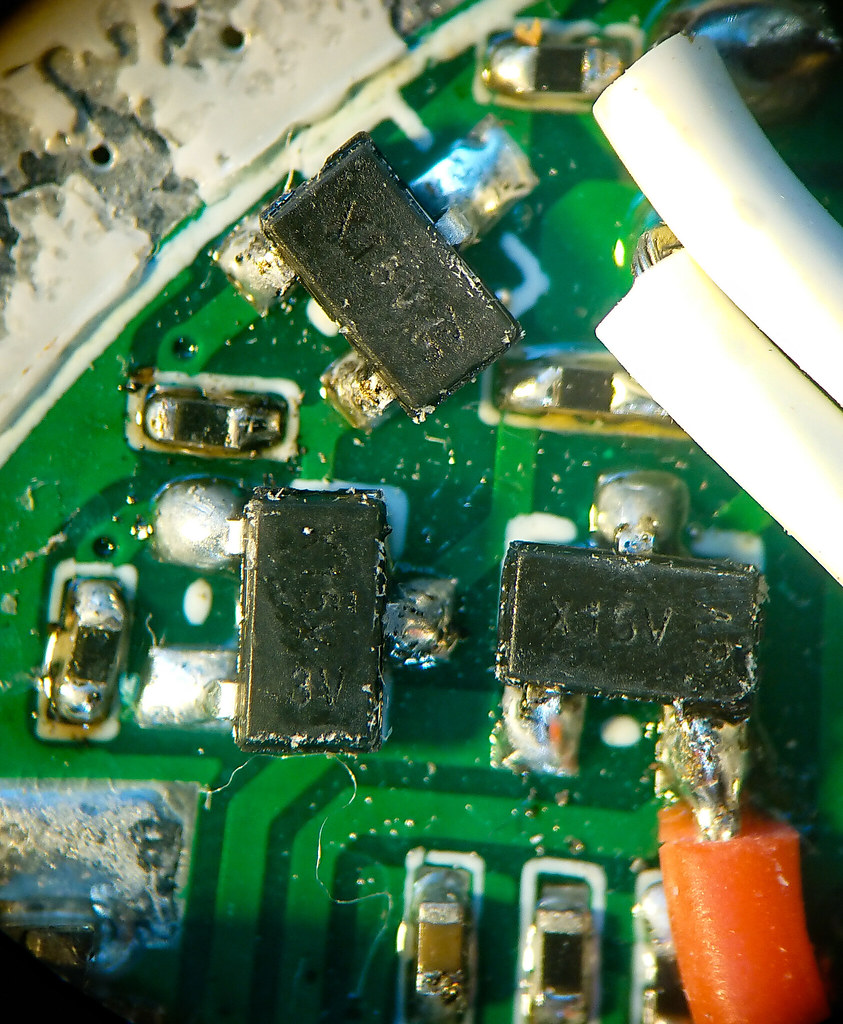
(these are transistors? I found these components on aliexpress marked X15V 3 K and those were transistors)

(stacking an extra cap. Is this the charging chip?. Stereopic)
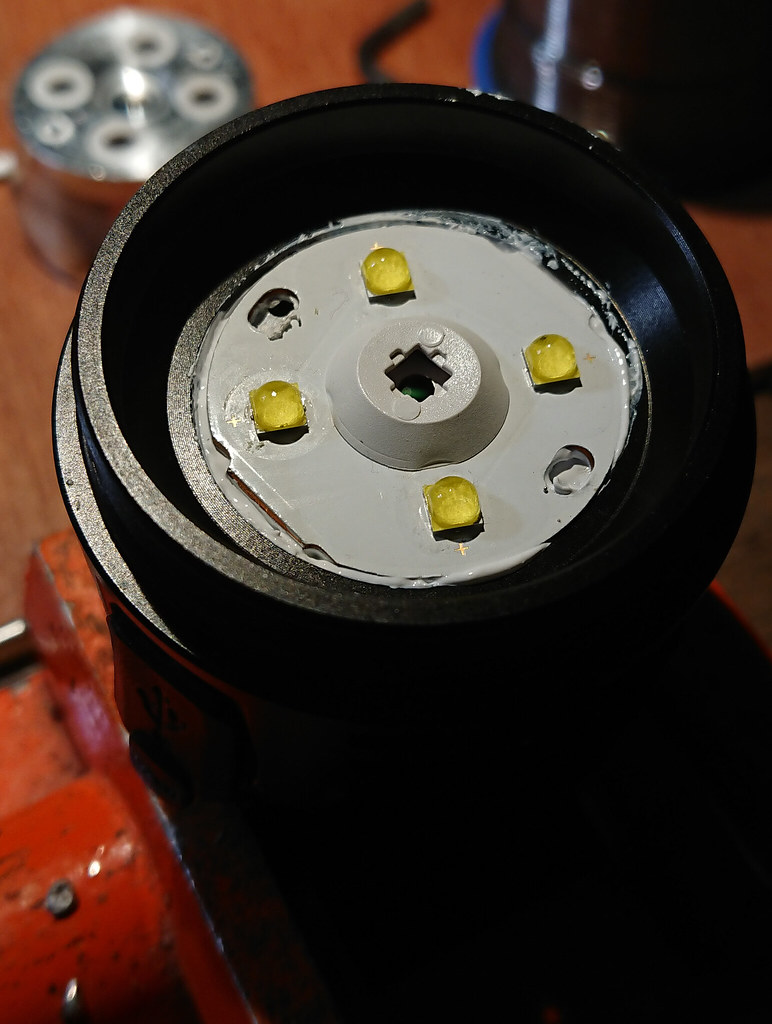
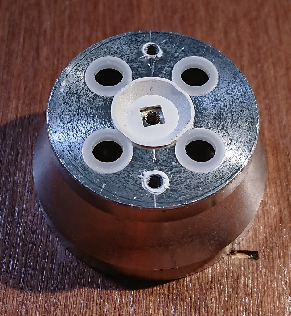
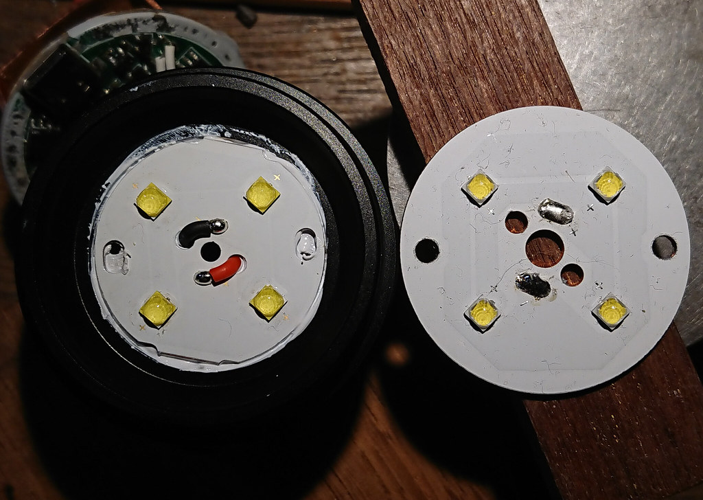
(the SP36 board is smaller than the Q8 board, but the same type, they just put the led+ trace on the outside instead of inside, but there’s clearance everywhere it could touch the shell)


