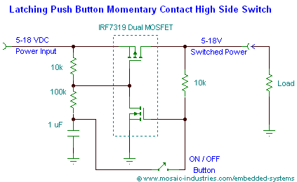
It is a 3A off/on soft latching power switch (we could definitely find a better higher current FET for sure) and design OSHPark boards for customization
Using a simple and cheap tactile button
Instead of having to find heavy duty built physical clickies with thick heavy contact wires use a simple FET to control the on/off function of the light
Imagine being able to have a 20A+ (or whatever the FET can handle) switch capability from a simple replacement board and using a quiet push button tactile switch
Looks like all that’s lacking is somebody to design a board find a MOSFET, solder it together and stuff it in a tailcap. Know anybody like that???
The quiet soft switch would be very nice, I’ve seen some tactile switches that do produce a click if desired.
Seems like the only current limitations would be the FET and the traces.
Could these also be designed to replace the momentary side switches with a remote mounted board?
um…wouldn’t that run the driver backwards, (reverse polarity)
I think problem with the schematic is it needs power to be on before it can toggle…since the driver is “off” and no current flow from the + side of the battery terminal to the ground (the body) it won’t have the required voltage to activate the FET’s
Only way to have this work “independent” of the actual battery in the flashlight is like RBD said above, it will need it’s own power source (aka the button cell) but that kind of defeats the purpose
Arrrgh…the longer I look at it the more I understood why it wouldn’t work as is…dagnabit, unless a CR927 was somehow incorporated into the spacer needed for the PCB or something
wait…I just tested my Ultrafire F13 and my SH98 (SK98 clone from ft)…touching the negative lead to battery - , and the positive lead to the body (bare metal) I get battery voltage, the light doesn’t turn on but the battery input voltage IS there.
I think if the input is connected to the flashlight body and the ground to the negative spring it might work…investigating further
Check it out yourself…pull the end cap, check with volts on multimeter, put the red on the body/threads/bare metal of flashlight, the black on the battery - and you will see the battery voltage but since no current flow the light won’t turn on…I do believe this is doable
The switch will need some voltage. Since power goes through the driver and the LEDs first then you won’t have full cell voltage to operate the FET. Mattaus was working on one I believe but with a coin cell. Side switch lights could use one. Don’t think this is worthwhile for most one or two cell lights. Maybe a 3s cell light where one or more of the cells has a pos terminal at the tail end of a battery carrier or a carrier modded with a pos feed to the tail.
This is a good idea, but it would work best if the FET is placed between the battery and driver.
This way you can connect to the positive (button top of the cell) and negative (ground ring of the driver). That way a coin cell is not needed.
I guess that most flashlights that have a small clicky switch on the side use a scheme similar to this one.
