Solarforce K3 Modded & Compared - Pics w/Vid *Pic Heavy*

This was NOT easy! I used a cordless drill and a dremel. Well, initially I cut the disk out with a large hole saw on the drill press.


Cutting the groove in the circumference was a PITA to do! But I think it will nearly double the capacity of this sink to remove heat, as it created much more surface area. I used 1/16, 1/8, 5/32, and 3/16 bits.

Nice. Have you thought about designing holes in brake discs? Any initial thoughts on how it works?

Looks a lot like a brake disc, but then, that’s exactly what they’re designed for too, isn’t it? I think it disperses heat through the extra surface area the holes and slot provide, just a guess.

LOL, I haven’t run it yet, just got done with it and got a shower to get all the aluminum dust off me. I was going to turn it down a bit, so the larger holes would have a portion cut off and make an anti-roll feature, but it’s all done by hand and not exactly concentric which would show more if I tried to do it that way. So I’ll probably leave it alone. Not something I’m good at. Stopping short of ruining something. :wink:

I’ve got it set up just like before , running 4.40A. Except now it has this huge chunk of copper running down into the L2P host. And now the heat goes into the top of the battery tube quicker, but between the copper and the outer heat sink, it’s showing 123.6º in 5 minutes instead of a little over 133º. So it’s about 10º cooler in that first 5 minutes. How much further it’ll go I don’t know yet. But it concerns me that the heat is going into that top cell, Anyone know what the danger zone is for a Li-ion temperature wise?

It did last year in a thread titled :
7135 drivers with higher voltages progress report: Next step 2s2p

I went as far as 3s XML’s from 3s liion using a nanjg 7135 driver. In post #14 DrJones kindly pointed out 2 different ways to achieve this. I used one and comfychair uses the other( note: before that I didn’t know diddly about either but it is apparently common to use Zener diodes this way).

The problem is that as with most of my threads anything useful is likely buried under piles of .

Not quite... under braking the pad material doesn't get worn away by friction like you'd expect, it's oxidized or converted directly to gas. That gas coming off the pad surface can get trapped between the pad & disc and reduce the surface contact, hence the holes and/or slots that give the gassified pad material an escape path. Kinda like the grooves in the tread pattern of a wet weather tire give the water an escape path so the rubber doesn't float off the road surface.

All the test results I’ve seen are about the heat dispersal on vented brake rotors. Ie: reduced brake fade after repetitive stopping due to overheating. If what you’re saying is straight up, then the OE brake rotors are endangering our lives and we could get a big class action suit going against the big 3 for simply not using vented rotors. Also, why all the brake dust if the pads are oxidized instead of worn?

Sports cars use em due to increased speeds creating, you guessed it, more heat under extreme stopping conditions. I’m not qualified to state that what you said doesn’t happen, but it’s not the primary reason for a sports car to use vented or drilled rotors. You might notice you can find Brembo drilled rotors under the performance tab, not safety.

Not anything like the tread pattern on a tire. That’s there out of necessity, safety concerns make it a must have feature to have tread on a tire. That doesn’t mean that treads, in and of themselves, give great rain performance. Only a few well designed tread patterns do that, and then only in conjunction with the proper rubber compounds and even then not for the life of the tire.

Drilled rotors, it’s all about the heat Baby! :slight_smile:

First board I stacked 8 chips for a total of 16 on board 7135’s. Second driver I only stacked 4 chips for 4.4A. Both times I ran into issues. The second time the light was working fine, ran tests last night everything was hunky dory. This morning the light wouldn’t work on high. Flickered. Low was really low, only medium seemed unaffected. So I put the first driver back in (I had soldered the negative lead to the emitter directly to the ground ring, shorting it and putting it into direct drive) and now am running Efest IMR18650’s at around 5.7A. The Samsung 20R’s pull around 8A, Panasonic PD’s in the same range as the Efests.

Not using the shorty cells as there’s no balance with the big aluminum sink up front, the longer set-up with the extension tube allows more grip room.

Vented rotors are indeed about heat dissipation, that's a very different thing than drilled/slotted rotors. Normal production cars don't have the tires or suspensions to generate enough braking force to run into the issues with pad offgassing, the tires will simply lock up before then. In normal traffic situations brake pad wear is from friction, but then in normal traffic situations you don't typically see drilled/slotted rotors being used.

A drilled slotted rotor is actually less heat tolerant than a solid or vented rotor, the holes cause uneven expansion and cracking is commonplace and their life is dramatically reduced. Not much use on a car where the braking force never approaches the level where the drilled/slotted rotors ever have any pad offgassing to deal with, no?

With Toyotas making 300hp, as well as most every other manufacturer, and the big 3 making street level performance cars with in excess of 450 horsepower and even bypassing NASCAR power levels at the top end…oh yeah, much use there is!

Camaro’s with Corvette engines routinely warp rotors when folks are playing, even burn up the transmission if taken to the track. I don’t know how folks drive where you’re from, but round here they use a car for all it’s worth! We do, after all, have a highway with the highest speed limit in the nation. :wink: Even our back FM roads have 75mph on em. Folks drive like the proverbial bat out of DC all the time, while talking on their phones. Fast take-offs with sudden stops are very detrimental to good braking performance, in any car.

Most all brake rotors have a groove between the contact pads with some internal vents, groove being cut into the rotor from the thin edge. This is obviously not what is being discussed, even though my heat sink also has that going on. The obvious drilled holes in the aluminum sink look much like a performance brake rotor that’s been drilled, although they are usually in a spiral pattern radiating outward from the center. And this effect is all about heat.

And yes, performance brake rotors get warped, cracked, even flat out broken!

My current toy is a 1200hp single turbo SBC, I've done cars professionally for more than 20 years both at the dealership level and non-street-legal level. Believe me, I know what it takes to break stuff and what it takes to fix it afterwards.

Ever wondered why some regular production brake pads have a slot cut in the surface? Doesn't that reduce the contact area, and therefore the friction? That slot in the pad material is for gas venting. The holes or slots in the friction surface of high performance rotors are there for gas venting, not heat dissipation. The axial venting in a street rotor is for heat dissipation. Some rotors are dimpled on the braking surface instead of drilled all the way through, an attempt at a balance between providing an accumulation space for the gas, and maintaining rotor integrity and durability on a road-legal car where the service interval is much much longer than a dedicated racing car where parts are replaced on a schedule regardless of wear or damage.

Most road cars with drilled rotors are just showing off that they have enough money to replace cracked rotors once a year, not that they are capable of anything approaching the performance level where the drilled rotors are actually beneficial.

Do you think this piece of aluminum drilled and slotted like it is will actually help the K3 disperse the heat coming from the honkin big MT-G2?
Fresh charged Panny PD’s just hit 7.12A. Aluminum brake rotor or no, won’t be able to run it long at that level!

I just ran it about a minute, heat wasn’t getting down to the battery tube when I turned it off…several seconds later, still off mind you, the heat is warming up the top end of the host. lol

The holes in brake disks don’t really add sufficient cooling surface area. Small holes offer more surface area but have poor air flow. Large holes have better air flow but decrease surface area.

A properly drilled brake rotor will have more evenly distributed pressure on the pads by having progressively less contact area (more overlapping holes) at the outer regions of the disk where the swept area is greater and faster. That’s where the most heat is generated and likely to warp. Holes also provide an escape for water. From what I’ve heard, during the first revolution after applying the brakes, the pads hydroplane until the water is wiped away.

As for the cooling effect on your light, convection works best with vertical surfaces. So, unless there’s some forced airflow, those holes will provide the best cooling when tailstanding.

Yes, of course what you built will help get rid of the heat (as long as it's in good contact with the hot parts on the inside), I was addressing how a brake rotor with superficially similar design serves a fundamentally different purpose! :)

What about one of these, with a hole bored thru the center to press-fit onto... whatever?

Might make slipping it into a pocket a little... uncomfortable.

The howstuffworks.com article you're paraphrasing is fundamentally incorrect. I guess in the internet age if something false is repeated by enough people it becomes indistinguishable from fact?

Sorry, care to explain? I didn’t read anything. I’m relying on memory from back in the race days, long before the internet age.

I simply wanted to add some mass to the smallish light to help it handle the biggish emitter and garishly huge power consumption. The bare disc didn’t do anything for aesthetics, so I went to immense difficulty to make it have form to follow the function.

This is all MRsDNF’s fault! Get him! He went ———-> that way!

Could someone please answer the question about this heat getting to the batteries? How much of a concern is that and at what temperature do I need to limit that top cell? I’ve seen 121º, much hotter just can’t be good for that top cell!

I had a similar idea to sammich a finned disc in a C8 but with the LED directly mounted to it. Where the LED sits, the disc will be in a good place to tap the severed C8 head for small screws.

I know heat decreases the life of Li-Ion but I’ve had the Li-Po variety with good air flow get far hotter than 121º from high discharge rates so internally, it was probably even hotter. I always remove my batteries to cool down after running my lights on high.

Well, since I’ve having some issues with my drivers and have gone to direct drive I’m trying to understand the Pros and Cons of each. Other than the modes, what does a driver bring to the table? Is it that it limits the amperage, say from a potential 6A to 3A and thereby prolongs run time? So it will produce less light for longer under regulation?

But with direct drive, it produces much more light initially then falls throughout the batteries useable life. Right? So the output is not consistent as compared to the drivers regulation.

Twice as bright for half as long, or half as bright for twice as long….kind of difficult to figure out what’s best!

For me, the problem seems to be that once you see and use 3000+ lumens, you WANT 3000+ lumens! 2500 is good, and I know it’s better for the light yada yada yada, but it’s an addictive thing isn’t it? Frankly, after that initial start time Wow! Factor, as it runs down a little it’s sorta ho hum….once it hits 2500 it’s kinda boring, lol. Nature of the beast?

I’m fairly certain that the issue with this last driver, run sanely with 4 extra chips at 4.40A, was one of my own doing. I didn’t trim the driver/pill to allow a snug fit but instead left it too tight and had to pretty much force it in. Made it a real bear getting it back out this morning, for sure! No visible signs of any problems, all the chips looked just fine, the 200 ohm resistor looked fine as did the Zener. So I’m pretty clueless as to what happened. Nonetheless, hi would only dimly flickr and lo was barely on at all with medium being the only regular setting. Regardless of cells used, whether in or out of the light. Hooked back up in direct drive, it seems to be just fine.

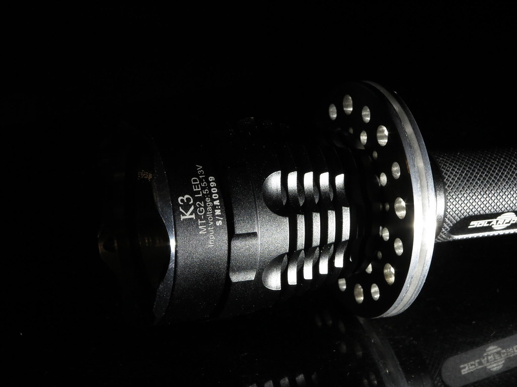
And this direct drive is the 16 chip board with the neg lead soldering to the ring, bypassing the control circuits…is this ok to run like this or do I need to take a different approach to direct drive?

Any suggestions greatly appreciated. Too much work on this one to bail on it now!

I went direct drive with my build so I didn’t have to do anything with drivers and to get the extra lumens. The benefit of drivers is the output is regulated, but since I’m using a 2x16340 IMR form factor, I wasn’t going to have good runtime anyways.