Solarforce K3 Modded & Compared - Pics w/Vid *Pic Heavy*

Being as how I’ve made more than my share of posts on the existing threads on this light, I figured I should start my own for the video and accompanying photo’s. So please bear with me on this, the 3rd such thread on Solarforce’s new K3 MT-G2 head unit.

For the record, this light is no longer in stock 1500 lumen form. Comfychair helped me make the mods with very generous and patient instruction on driver how-to in order to get a standard Q-Lite 105c driver with 8x 7135 chips pushing 3.04A to run off of 2 18650 cells at 8.4V with 12 chips and run 4.40A through my MT-G2 for some 2400 lumens of awesomeness! :slight_smile:

Let me address this mod first. The driver no longer has reverse polarity protection, nor does it have over discharge protection. What it does have is oomph! By removing the polarity diode at the base of the LED positive lead and replacing it with a 200 ohm resistor, and by stacking a 4.3V Zener diode on the capacitor on the spring side of the board, this anassuming driver is now the heart of a beast!

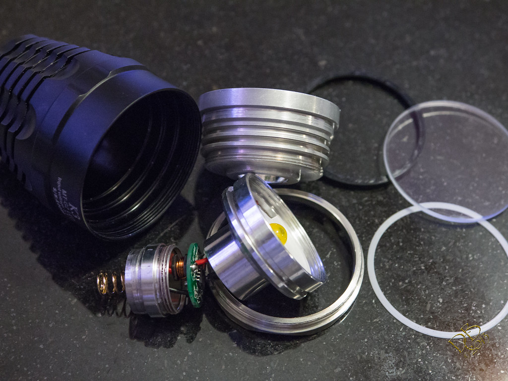
The breakdown

The stock driver…note that I added a 6.5mm x 18mm slab of copper up inside the pill under the emitter in my mod for heat sinking
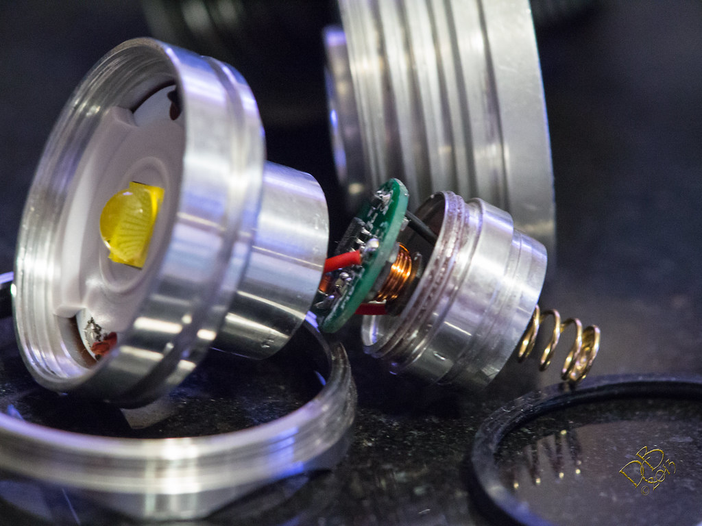
Perspective on the parts

Another angle

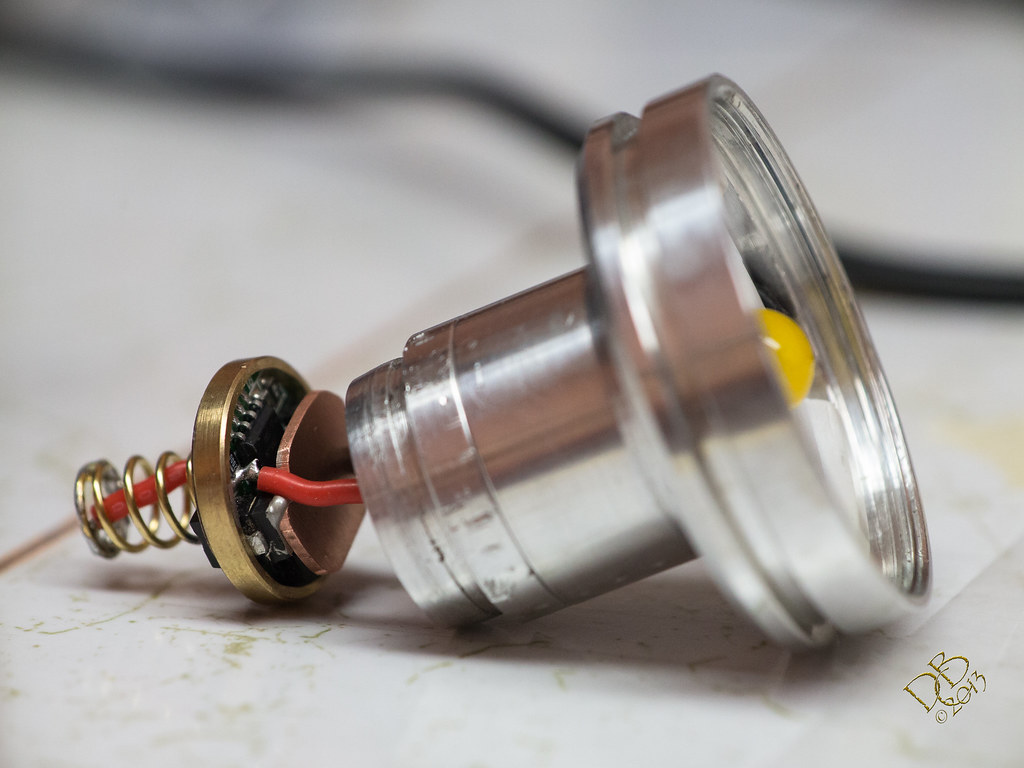
32mm slab of copper under the MT-G2 emitter, thanks Solarforce! :slight_smile:

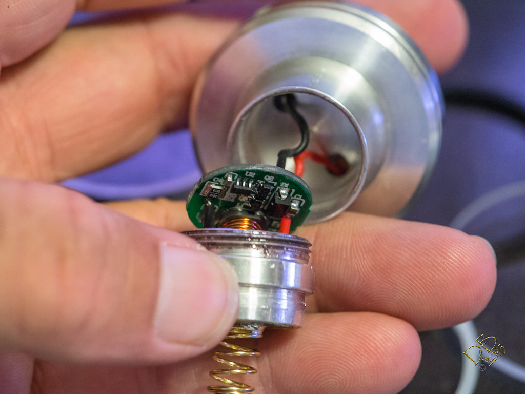
Trying to come to grips with what needed to be done to the driver
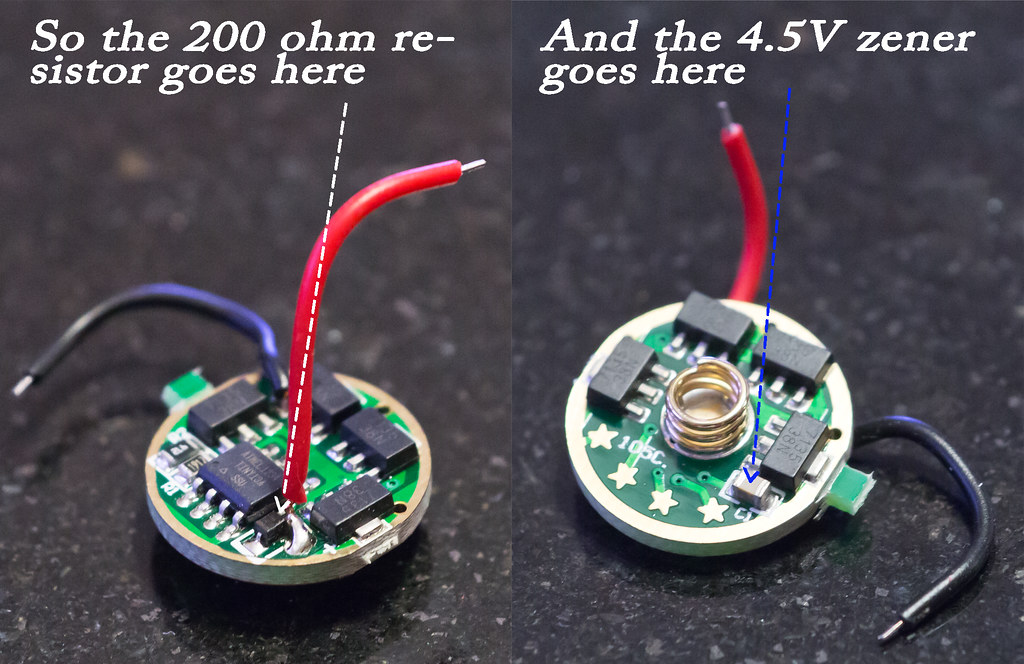
The Q-Lite 105c driver, modified
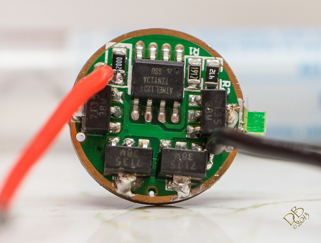
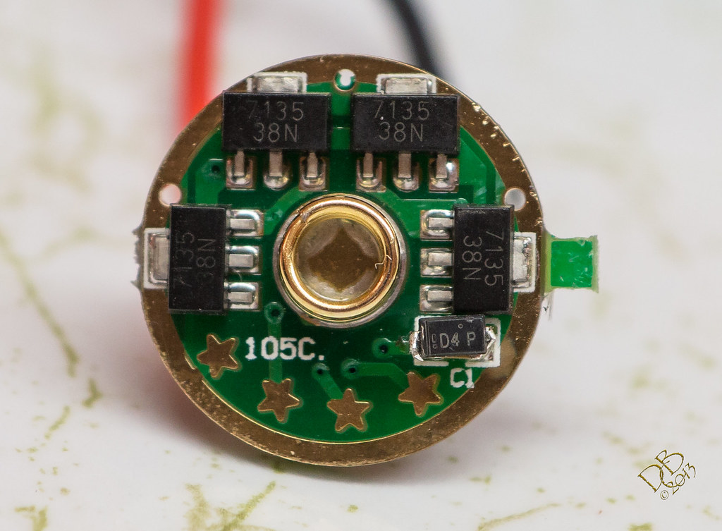
The copper plug in the pill for heat-sink, glued in with Arctic Silver Thermal Adhesive
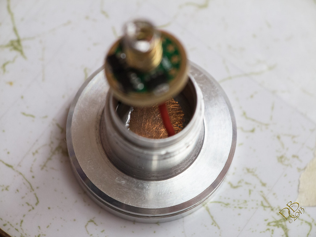
Added copper plate on top of stacked chips for heat dispersion
This animated GIF shows a before and after of the stock vs modified K3 In looking a straight line towards the red oil drum, the pavement at the bottom of the picture is 15 yards from the camera, the edge of pavement further out towards the drum is 28 yards from the camera. G1X zoomed in to 112mm equivalent. (4x optical)

And this video shows comparison to A) The L2P running an EDC+ Triple XP-G2 at 720 lumens OTF B) The Solarforce S2200 (updated 7:18PM 8.3.13)

http://www.flickr.com/apps/video/stewart.swf?v=109786

Here’s a line-up for comparison purposes, featuring (1) Maglite 2D with Western Robotics Voltage Monitor and running 2 32650 cells powering an SSC P7, (2) the Solarforce S2200, (3) the Solarforce K3 with L2P host and an extension, capped with their 2 pronged SS forward clicky tail switch, (4) the Solarforce M3 on an L2P host…modified with XM-L U2 emitter de-domed and on a SinkPAD, driver swapped to one of Eriks 5 mode wonders and bumped with 2 more chips for 4.28A output, capped with their 4 pronged SS forward clicky tail switch, (5) a generic L2P host with no text carrying an EDC+ Triple Nichia 219, and (6) a Solarforce P1D with el cheapo 800 lumen XM-L2 drop-in.

The K3 standing up to it’s big brother, the S2200
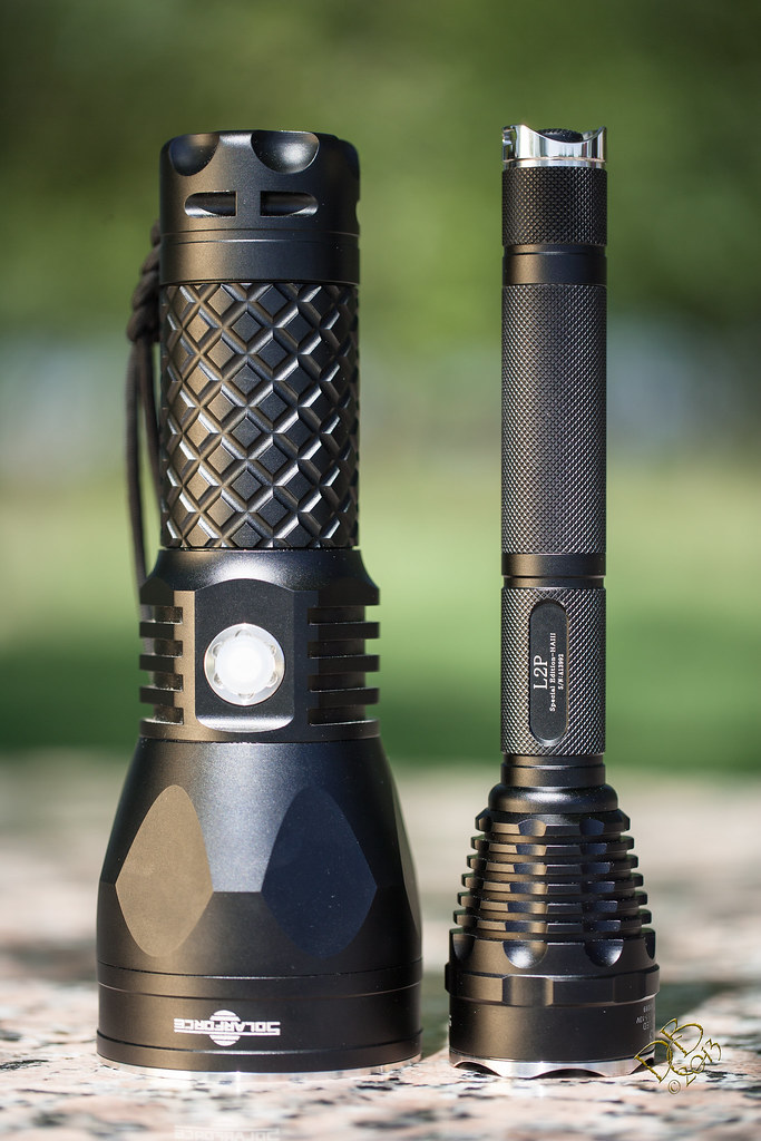
Side by side, those MT-G2 emitters sure are pretty!
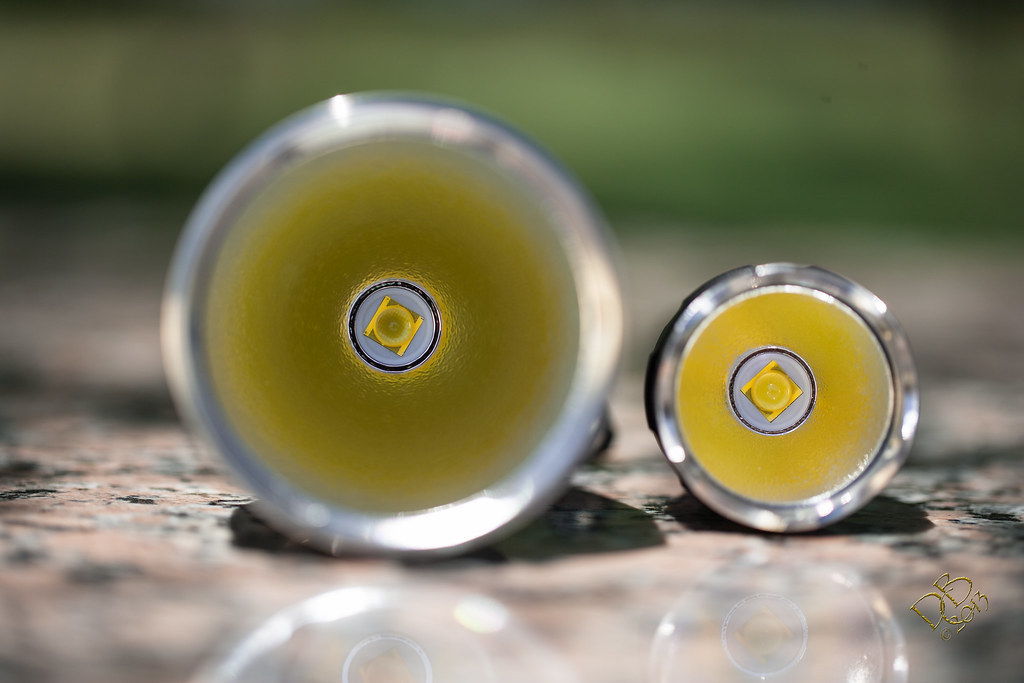
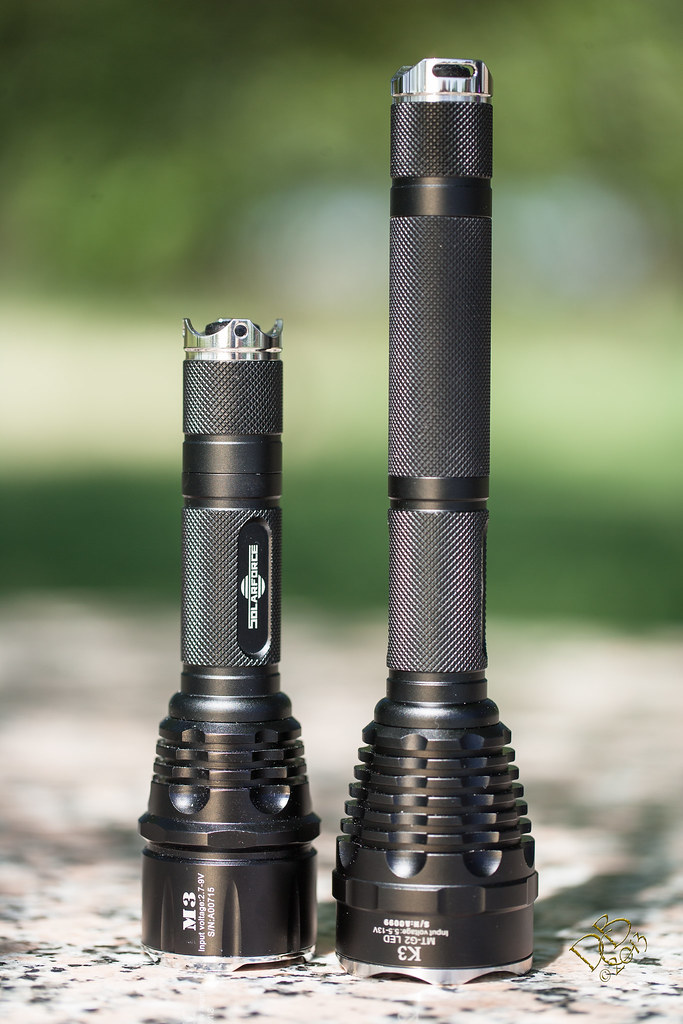
Now standing up for it’s little brother, the M3 (who now needs no help and stands pretty proud on it’s own!)
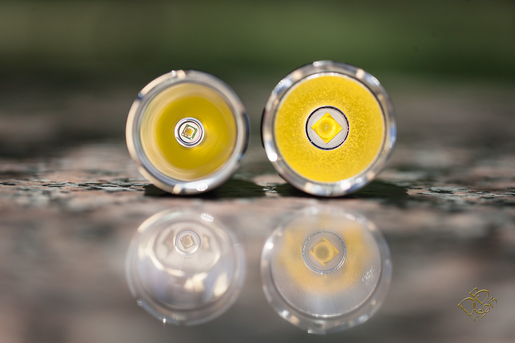
The MT-G2 as compared to the M3s dedomed XM-L emitter
The K3 and M3 go head to head

SSC P7 in a Purple Maglite vs the K3 vs the P1D
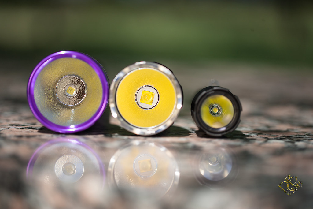
SSC P7 Maglite vs. the K3 vs. the M3
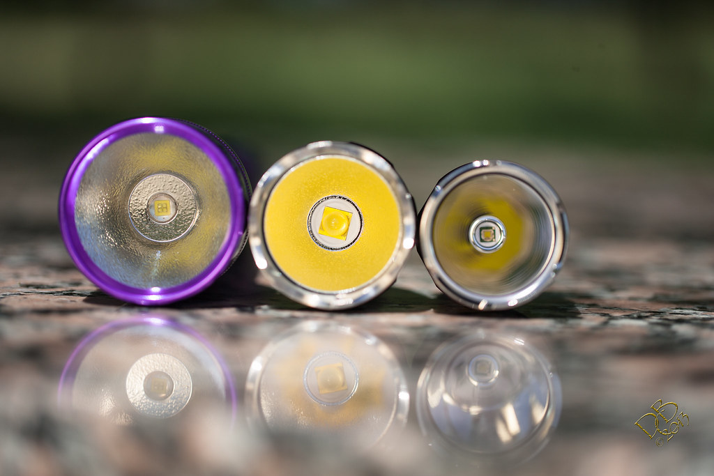
The Solarforce P1D trying to measure up

The L2P w/EDC+ Triple Nichia 219 vs. the K3 vs. the P1D

I’d like to take this opportunity to thank my devoted camera crew. My wife Mary who handled the lighting, my buddy Shadow who so studiously checked all the equipment and made sure to oversee every move made (thanks Buddy, my leg, hands, and 1DsMkII are now spotless!) and Mr. Henry Yellowjacket who generously provided the Texas Pink Granite table top for shooting and did not kill me. (I’m allergic and he was about a foot from my crotch setting up the shots)

Awesome job!!! Thank you for sharing. The S2200 looks awesome!! The K3 is very nice also!

Very nice my friend, VERY NICE! And the K3 isnt that much bigger than the M3, but is MUCH smaller than the 2200. With all that output in such a small package that is a KILLER modded setup you got there. Beam shots and video are A+ too!!

Have you done any measurements of actual amperage and voltage thru the emitter? If the driver is actually giving 4.12 amps to the led, then the voltage should be somewhere just under 7 volts. It would be interesting to know.

That light is so bright in the first photo, it made the black car swell from the heat and turn white.Wink

My daughter was here in her dark blue Honda Civic when I took the pics when the K3 was stock. My white Dodge Caravan took her cars place for the pics I took day before yesterday.

I haven’t taken those measurements. Not sure I know how. Or maybe I’ve seen it talked about here but am scared to do what it takes. lol Do I have to take a lead off the emitter and run it through my DMM? Essentially inserting my DMM between the driver and LED? That 32mm slab of copper makes soldering leads difficult, even with my Hakko 888…I had to crank it up to near max to get enough heat through it to make connections.

Thanks guys. Similar output with the nod going to the K3 in sheer total light, but the S2200 out throws the K3 and out lasts it as well. With these mods, the little K3 gets hot…fast! The entire video above is 4:13 in length, the K3 wasn’t running the entire time but when I turned the camera off the light was very warm, almost too hot to hold at the head. At least I know my heat-sink and pill wrap are doing the job of taking heat to the head. :wink:

The pics are uploaded to Flickr in High Resolution, click the pick to open it in Flickr, click it again to enlarge, then right click to select original image size or less for a very close detail shot. :wink:

Has this driver modification been discussed before here? If so can you provide a link? Seems very interesting.

Nice job :bigsmile:

Where do you source the resistor and zener? I have a few 105c drivers here, so might order a K3 to mod.

Thanks for sharing this.

But I think there’s a zener right there on the original driver, so all you’d need in addition is a 200 ohm resistor…preferably a thin film style as it fits neatly in place of the polarity diode.

1
RoHS: Compliant through Exemption1

71-CRCW0805200RFKEB
CRCW0805200RFKEB
1/8watt 200ohms 1% 07/29/13 10 0.048 0.48

2
RoHS: Compliant2

512-MMSZ5229B
MMSZ5229B
4.3V 0.5W Zener 07/29/13 10 0.149 1.49

Really expensive stuff, huh? Seriously in multiples of 10 they were cheaper than a soft drink.

Thanks for sharing.

Nice photos!!

Appreciate it.

Ok thanks :bigsmile:

Don’t get me to lying, I did read how to do it once, but I don’t remember where.

Thanks DBC. Looks like you have yourself a real nice light there. The emitter measurement at the led is no different than taking a measurement at the tailcap. Remove the earth wire to the led and run it through the meter and back to the led. You know that you really do need a lathe. When is it coming?
OL. I have it on good authority that Buddy the white dog was black before this flashlight shootout.

Wonderful pictures! And a nice mod!

Looking forward to emitter current measurement. :)

pulling a lead from the emitter and having to solder it back on just for that reading? Doesn’t the tail cap reading say enough? That 32mm copper star on thick aluminum with a 1/4” of copper underneath it sure makes it difficult to solder a lead!

If you think it’s worth getting that number, I’ll consider it. But really, what’s it going to tell us that 4.05-4.15 at the tail doesn’t say? I suppose I’d also have to run it in Voltage configuration to see what the Vf is at x amperage reading while I was there, right?

I’m still new enough at all this that when I get a build done and it works I’m scared to mess with it in fear it’ll fall off the cliff it’s been perched on the edge of.

With my limited testing and experience you will probably get between half and two thirds the current reading at the led compared to the tailcap which has something to do with the higher forward voltage. You get a lower current measurement than you would if you had an XM-L led in its place.

I’m not sure if you have seen this thread.

to really get an estimate on how many lumens it’s putting out is to take an amperage and voltage reading directly from the emitter?

Here’s some more numbers for the numbers freaks…start at 91.1º and in 5 minutes it’s at 133.3º. Pulled cells, top cell showed 109.9º at the positive end. The host was sucking heat from the head at an alarming rate, which is why I pulled the cells immediately. It get’s hot, it spreads it, but man it’s bright for that 5 minutes! :slight_smile: Cells went down from a freshly charged 4.20 to 4.03.

I looked earlier and didn’t find it and got distracted. Sorry bout that. Try reading this thread and I believe you’ll find the answers or the people that have them.

Ah thanks! And no problem. I forgot 7135s don't have the 6v limit like the MCU, but they are all about how much voltage they can drop before burning up. Now I just need to think about how that zener diode and resistor work to drop the voltage to the MCU. I'll have to break out my "Electronics for Dummies" book again.