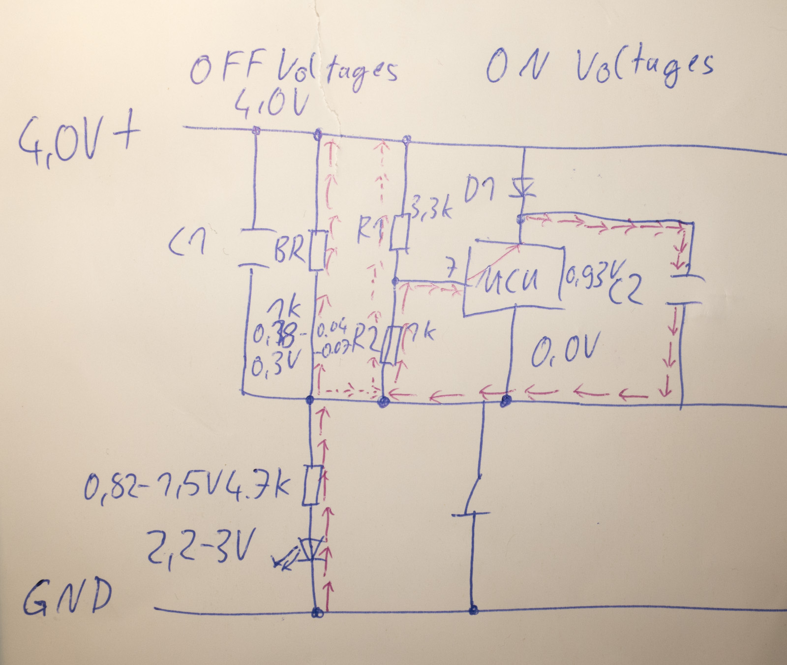
Ok, nice red arrows but your mcu current path is wrong. Pin 7 has mega-ohms of resistance. The electrons flow back to the mcu through the mcu's own case conection, not through pin 7. The C2-mcu circuit is completely isolated and just floats on the case ground. It has nothing to do with anything. You can just remove it from the picture. You can also remove C1 as it has no affect in DC when the led is powered.
You only need BR R1 R2 Rled and the led. But I already wrote the simplified circuit above.
You can do it either using voltage ratios or current, or both, and it all better get you to the same answer. I worked out the math fully rigorously above without direct need to ever reference current but of course the voltage I imply for a divider are derived from "ohms law" as it gets called. And the led voltage is probably closer to 2.1, not 3 and could even be less at these currents.
Anyway, with the 1K BR and 4.7K Rled in your image, you get a total series resistance of 5.5K, and yes OTSM should work in THAT configuration, and the LED probably should too. The q8 is using 15K series resistance and still getting their two green LED's to light usually.
The OP started with no BR and said the LED only lit with Rled down at 220ohms. That's a total series resistance of 4.5k, but with too much of the voltage drop above the case, which is why OTSM is not working and is where all this started.
5.5k isn't much more than 4.5k. So yes your configuration could also work, probably should usually. Will it work for g_damien's LED? If not then a 1K bleeder and 3.3K LED resistor certainly will, because that puts him back below 4.5K where he was and still keeps the voltage drop situation ok for OTSM.
Traditional lights needed the bleeder for different reasons than this OTSM light does. They needed it because R1 was 20k. In this light the LED can work with no bleeder at all and the LED resistor only fine tunes brightness or also isn't needed at all. You need the large led resistance in this light and compensating BR exactly because of this OTSM voltage issue. Although OTC has a similar issue, and probably wouldn't work well with no LED resistance at all, but being analog and calibratable it has a higher range of tolerance. Downside being it required calibration.
Anyway,
Bottom line: Try lexel's 1k BR and 4.7K led resistor, OTSM will work. If the light doesn't light up, try a 1K BR and a 3.3K led resistor. That should certainly get it all.
He did not use a bleeder at all, he used a 220Ohms tail resistor to get the LED light up, so the full tail current flew through the R1 and R2, of course that lifts the voltage above R2 over 0.8V and OTSM stopped working
"The OP started with no BR and said the LED only lit with Rled down at 220ohms. That's a total series resistance of 4.5k, but with too much of the voltage drop above the case [ie across R1+R2 just as you're saying], which is why OTSM is not working and is where all this started."
Yes, he did not use a bleeder but he still had 4.5K resistance in series with the LED. I agree that that configuration causes a bigger voltage drop from Bat+ to case (it matters not how that voltage drops, through R1/R2 only or through an effective combination of R1+R2 with Reff, only how much voltage drops, as determined by the ratio of that combination with Rled, you can achieve the same adjustment by adding a BR or by lowering R1 and R2). Anyway, you seem only able to think about things in terms of current in separate paths. There are other, simpler ways to get there. In the end you aren't even disagreeing. The voltage drop across the BR is identical to the voltage drop across R1 and R2 and it is determined by the Ratio of the total effective resitance, 1/(1/(R1+R2)+1/BR) to the Led resistance, regardless of how you create that effective resistance. You can think of currents if you want, but you get the same answer, as you did. If instead of adding a 1K BR you make R1+R2 total to 1K, ALSO all of the current will go through R1 and R2, but the values of R1 and R2 are lower, so the voltage drop is still the same. Same total effective resistance makes the same voltage drop, regardless of what fraction of the current goes which way.
No bleeder can light the light equally well, but causes voltage problems on R2 that breaks OTSM. Which is exactly what I started out saying, and what I said again two posts up. :facepalm:
So we agree, you can light the led different ways, but some of those ways will cause voltage problems that break OTSM.
The case voltage is irrelevant as you have 2 separate voltage sources, I tried to explain it to you multiple times
You have to calculate either the voltage drop ratio between BR and the Tail board
This leaves you to 0.18-0.3V in my example, this voltage also applies to R1+R2 as it is parallel to BR or
You have to calculate the current flowing through the tail LED, this includes all involved Resistors and the Diode
Then you calculate how much of that current flows through R1+R2, which is obviously less than through the bleeder, so you can calculate how much voltage drops over R2 U=R*I
In both cases you have to calculate the relative voltage lift between R1 and R2 by the current flowing through them or total voltage drop for the parallel part of the voltage divider BR,R1,R2 and tail board
The more voltage drops on the tail board the less is R2 affected
No I don't have to calculate the current flowing through the LED (well, not to understand if OTSM will work). You have to, because you can't understand the other simpler ways of getting to the same answer. That's not about what I have to do. You're finally reaching the same conclusions but still think you're arguing with me.
Yeah as you never calculated your guesses how high the relative voltage lift over R2 is with a BR and Tail LEDs
In my example it is 0.14-0.23V when the switch is Off
As soon as you turn on the switch you deal again with a common ground and the value of the bleeder has no effect on R2 at all and tail LED is shorted
Your example is not the problem cases that started all this. Yes I did calculate and in that example you are right and it is EXACTLY what you get if you use my math on post 299 (except that I would never assume the LED voltage to be as high as possibly 3V). You' seem h3ll bent on just arguing with me. And you are right that without a BR the pin voltage is much higher (although it is nothing to do with current all going through R1 and R2, you can fix it just by lowering R1 and R2 instead of adding a BR and still get all the current going through them. Anything you can achieve with the BR can be exactly achieved without it too). You keep saying I'm wrong and then eventually saying the same thing as me. You said my circuit was wrong, and then drew the same circuit. You said, voltage across R2 isn't an issue, and then proved that in the g_damien's case the voltage drop across R2 is too large. lol. The end result is you've caused this mess all over your nice thread.
I hate vague confusing circular arguments especially when there's no actual disagreement.  Math exists for a reason.
I will have no further discussion on this that doesn't address flaws in the equations here:


+4.1V ----------------
          |         |
          |         |
          |         R1
          |         |
          |         |
          BR        |--Pin7
          |         |
          |         |
          |         R2
          |         |
          |         |
   case   -----------
                |
                |
                |
              Rtailcap
                |
            tailcapLed
                V
                |
"Grnd"  -------------


but the led is just 2.1V so let's remove it (and lower total voltage)
2.0V ----------------
          |         |
          |         |
          |         R1
          |         |
          |         |
          BR        |--Pin7
          |         |
          |         |
          |         R2
          |         |
          |         |
   case   -----------
                |
                |
                |
              Rtailcap
                |
                |
"Grnd"  -------------


Now V2=R2/(R1+R2)*(2.0-Vcase)           eq. 1.

      R2/(R1+R2) is specced at about 70%.

But what is Vcase? Let's make an equivalent circuit:

+2.0V ----------------
            |
            |
            |
            |
            |
            Reff
            |
            |
            |
            |
            |
   case-----------
                |
                |
                |
              Rtailcap
                |
                |
"Grnd"  -------------


Reff=1/(  1/BR + 1/(R1+R2))    eq2.


Now, what is vcase?  It's

2.0-vcase =  2.0* Reff/(Reff+Rtailcap)   eq 3.


Subbing 1 into 3:

V2= R1/(R1+R2)*2.0*(Reff/(Reff+Rtailcap))

or using the 70% spec
V2=  0.7*2.0*(Reff/(Reff+Rtailcap))

If Reff is too high compared to Rtailcap, V2 becomes high.

Notice it makes NO difference how you create Reff.  You can
use a BR or not to get the same Reff and you can still get V2 the way you want.
It also makes no difference what fraction of the current goes through BR vs R1 and R2, so long as you get the right Reff.

But what about current?

I= 2.0V/(Reff+Rtailcap)

Just increase or decrease the value of EVERY resitor by the same factor to adjust led current.
It won't change the ratios and won't change V2.  It's a completely separate issue.
Of course if you only want to change BR and Rtailcap, you'll some intuition and guess and check,
or to work the algebra that way, but these equations will tell you the result of your choice.

The total current only affects the solution in that it affects the true LED
voltage a little, and the final scaling of all resistors. But if you know the target
current before you start that doesn't matter because you know the target LED voltage too or close enough at least,
and once you do get the right current, your LED voltage assumption will also be correct and the solution consistent.

Done.
And repeating this here for the benefit of g_damien:
Bottom line: Try lexel's 1k BR and 4.7K led resistor, OTSM will work. If the light doesn't light up, try a 1K BR and a 3.3K led resistor. That should certainly get it all.
Yeah... that's why it's the SECOND choice. Yes it goes up, but not enough to break OTSM, yet hopefully enough to make the light then work, which is what I said.
I could find another combination by modifying R1 and R2 to get the same current without it going up. I could (you can't, you don't know how) even do that with no BR at all. But you don't need exact solutions. There's a wide tolerance. You can have BR equal to Rled and OTSM probably still will work fine, as I already said.
You wrote that it is the OFF level on Pin 7 from R1 and R2 which is 0V when you hit the switch which detects that the switch is pressed
Then you say that lowering the tail resistor to 3.3k would make this detection better, but it increases the effective voltage detected at pin7 as the tail current gets higher, the higher the tail current the higher the current over R2 which gives a higher reading than 0V
Lets see what happens if we increase the tail LED resistor to 15k Ohms
Then the voltage over R2 drops to 70mV
U=4V
Vf LED=2.2V
BR=1kOhms
Why should a Tail LED should not light up at 480uA current, they light up at a few uA?
This discussion was about OTSM not working with tail LED, this simply is recognized by not being able to switch modes