Component tester Multifunction Tester T1
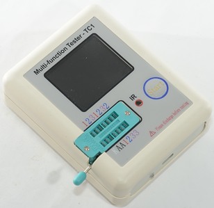
This tester has the usual component tester and a Zener section with higher voltage, components are connected to the ZIF socket.
I found it on ebay at a seller called tomtop_sales
How does it look

It was delivered in a plastic bag.

The tester includes a usb charging cable, clips, 3 loose pins and two components to test (led+capacitor).

The clips are not very good, they cannot close around small pins.

The charge input is a micro usb connector with a led to show charge state (red=charging, green=done).

Nice layout and labeling.


I had to remove four screws to open the box.
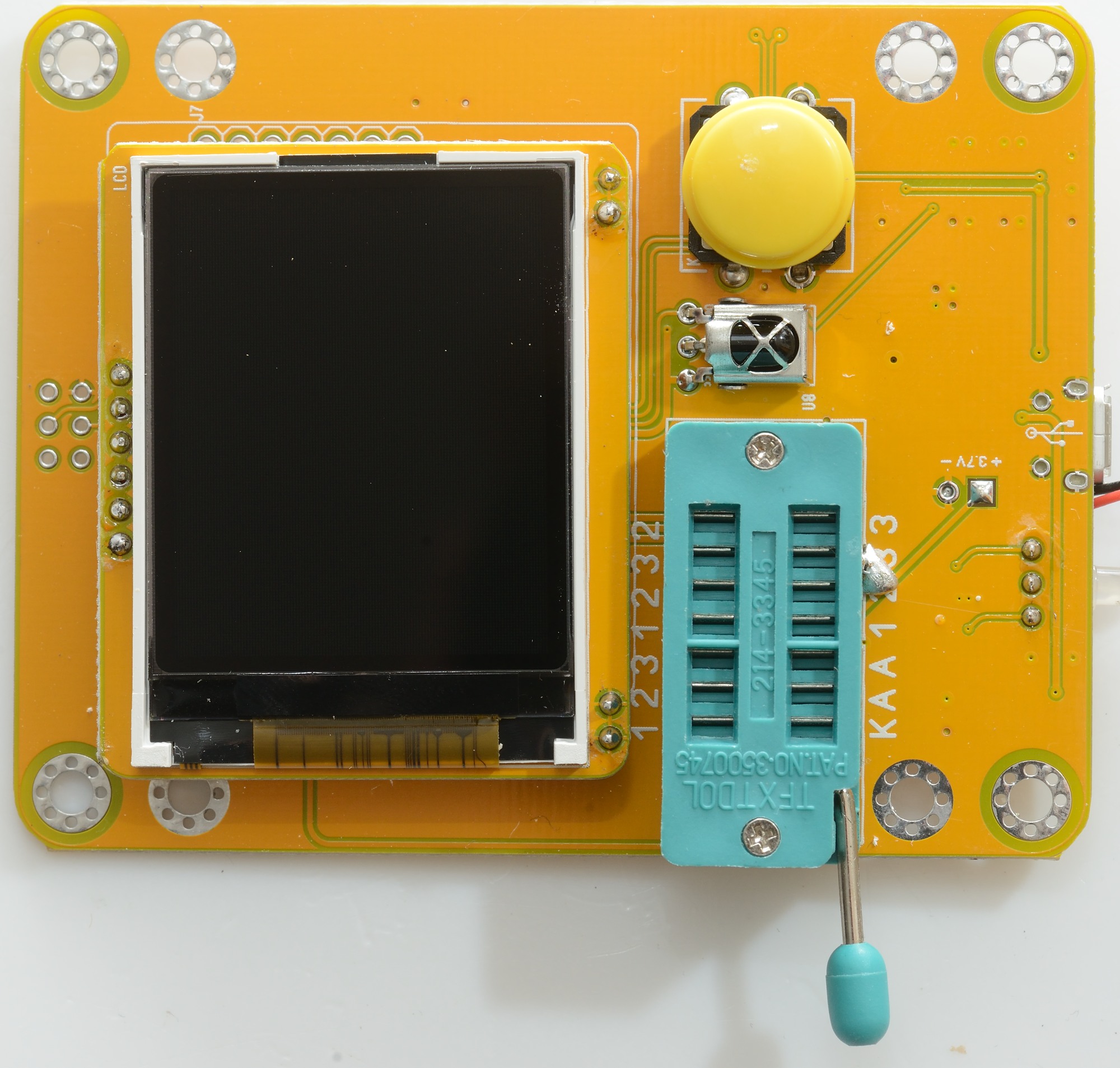
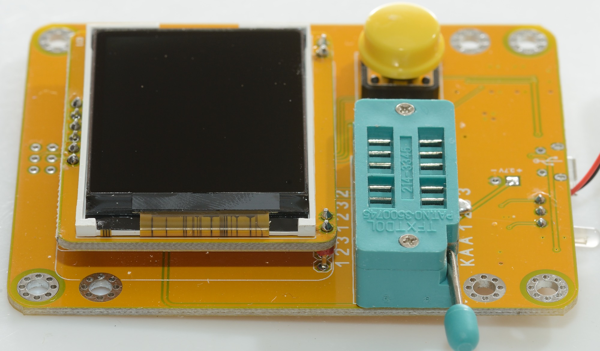
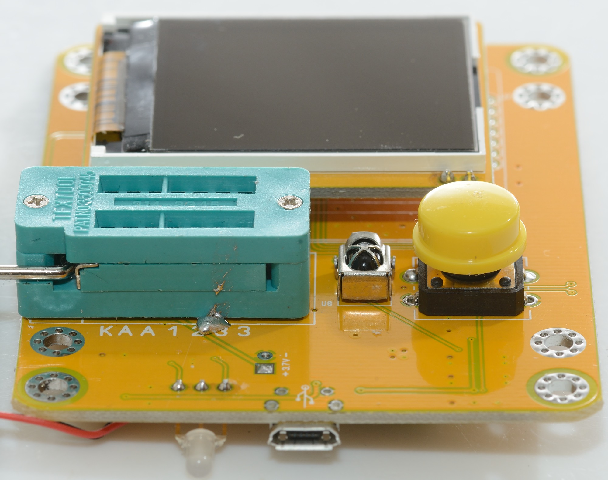
On the top side of the circuit board is the display, the ZIF socket, the button and a IR receiver.
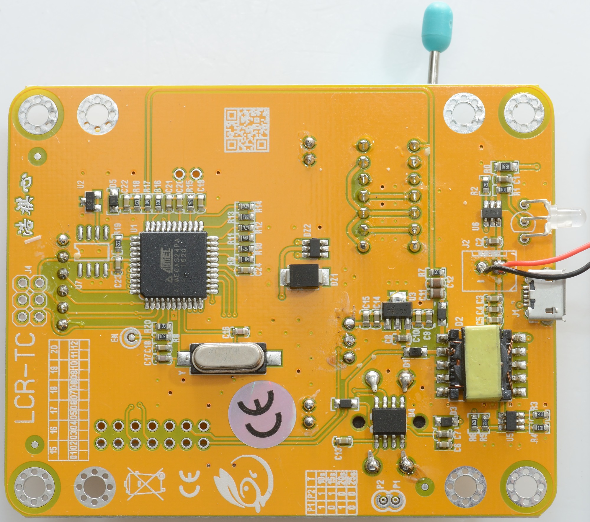
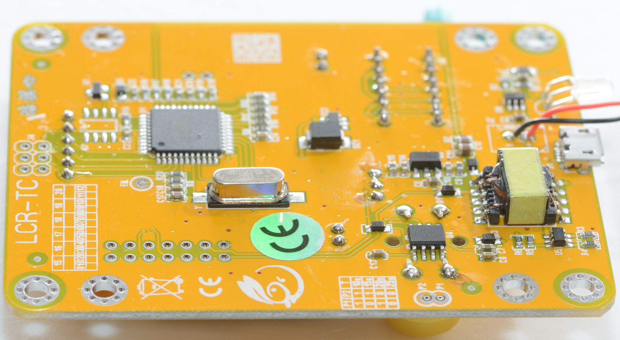
On the bottom is the microprocessor (U1: ATMEGA324) with a 16MHz crystal (Y). To get the LiIon voltage up there is a boost switcher (U5), a transformer with two outputs, one for 30V (D2) and one for 5V (D1), the 5V is regulated (U5: 78L05).
The chip below the switch (U4) must be some sort of power control and the charge circuit (U6) is mounted near the usb, led and battery connections.
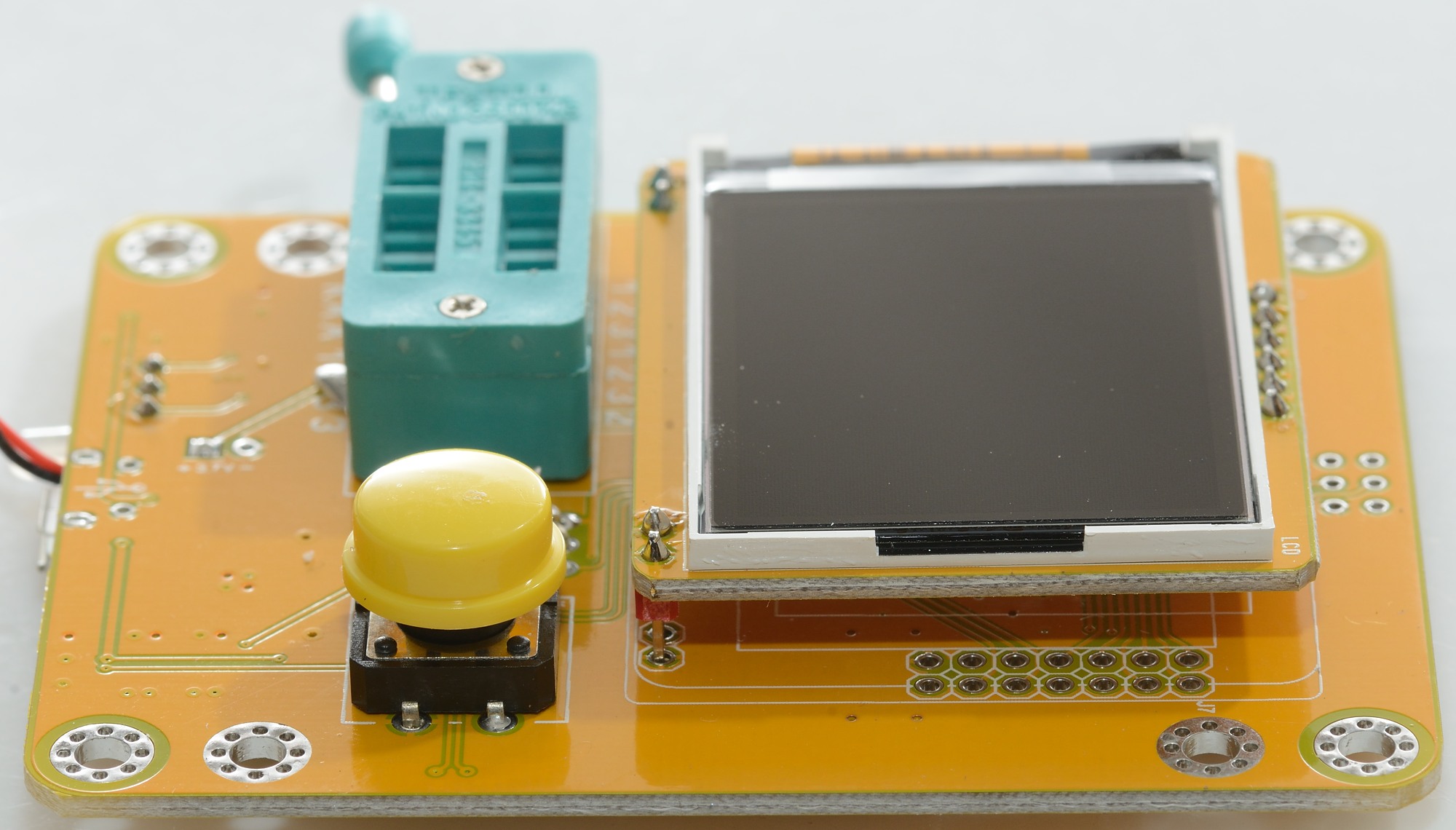


When powering on the display shows the LiIon battery voltage and the layout on the ZIF socket (very nice).
Resistors


I did not run a calibration cycle before testing, but it would not have made the low ohmic measurement perfect. The problem is contact resistance.
The red dot on the yellow top is because the IR receiver is seeing a signal, probably from my camera flash.
Capacitors


Capacitors looks fine. It is interesting that it can show 0ohm for ESR, when a shorted input in resistance test show 0.26ohm.
Inductors


This type of tester is not good at small inductors.
Diodes


3 of the pins on the ZIF socket is a special Zener diode tester and makes it possible to test Zener diodes up to 30V.

The difference between Zener voltage, measured voltage and rated voltage may be due to difference in current. Here I did a curve of the 2.7V Zener on some professional equipment (Keithley 2460), a simple tester could say anything from 2V to 2.9V for that 2.7V Zener, depending on test current.
SCR (Thyristors) + Triacs


The tester can only work with small triacs and SCR or it will show a wrong type.
Specifications says trigger current must be below 6mA.
BJT (Bipolar junction transistors)

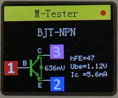

Transistor test works fairly well, but Darlington transistors with a BE resistor will show way to low hFE.
FET (Field effect transistors)


MOS works fine, but I had to skip the SMD parts.
IGBT (Insulated gate bipolar transistor)

Is supposed to work, but did not work with my test transistor.
Voltage regulators
Not supported
Batteries/voltage


This test is not reliable, sometimes it shows a low voltage and sometimes the correct voltage.
Remote controls


It will decode Hitachi remote controls according to specifications.
it worked with my Panasonic remote and with Chinese remotes for lamps.
Technical details
The tester uses 5 volt when testing, except Zener voltage output that uses up to 37 volt.
Conclusion
This type of tester is very good at identifying a lot of different parts, but it cannot do precision measurements.
The addition of a Zener tester is a good improvement, but do not expect it to show the precise Zener voltage.
The IR decoder is a bit limited, but for DIY with some of the cheap Chinese remotes, it can be very useful.
The voltage/battery measurement is not reliable, a DMM is much better.
I like this tester much better than the loose circuit board versions, but it lacks an area for SMD parts.
Notes
This tester is based on this design, but with a added 30 volt supply:
Original design article in German
Improved design (czech clone)
Software
It is possible to find a manual for this tester on the internet.
About the testing of testers
Thanks, HKJ :+1:
I’ve been thinking about buying one of these as a component tester, given my low budget, so it’s very helpful to know that it’s not particularly accurate. I’m still tempted to get one as a “mystery component” identifier, though ![]()
That way, I could quickly find out what the mystery component actually was, before subsequently determining its parameters by more accurate means.
Thanks for the review HKJ.
For the money I believe you get a lot with these component testers. This one is a bit above average due to the Zener test and the box with a rechargeable battery inside.
Hello!
I have Multifunction Tester-TC1.Transformer is for change.What are the transformer data? Some time ago I checked a capacitor before it is discharge.I suppose I will have other faults on the PSB board.
Thanks!
The transformer is used for the high voltage for Zener diode test. A charged capacitor will burn the microprocessor.
Hello!
In case of failure, the U5 (78l05) was very hot.
Thanks!