Thanks so much. I’ll start with just the top 7135 and I’ll keep trying until I get it all figured out. I’m excited to be able to put these together to really feel like I’m building the light! And I really can’t thank you enough for the work you put in to make this possible for people like me that are just beginning to learn about it all!
Hi Texas Avenger and Pwsmith.
Today I built a 22nmm TA driver for my Convoy S11, and initially the driver was shorted and the modes didn’t work. The same simptom described by Pwsmith.
As TA alerted, a shorted 7135 was the culprit. It was the bottom 7135 oposit to the FET. There are many vias between the FET and the bottom side of the driver. I removed only this 7135 and used a solder wick to remove the solder, and reflowed the 7135 again. Instantly the driver started to function.
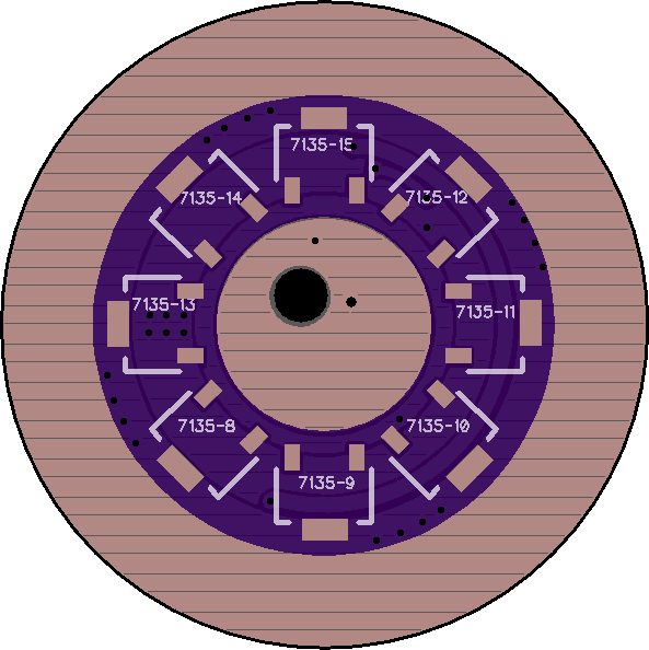
I then discovered that the 9 7135 chips on the driver were delivering only 2.5 amps. I put some solder paste in all the bottom 7135 and reflowed then again with a hot air station. Now the 7135s are providing the expected 3.1 amps for the maximum regulated mode.
Finally, I set to 180 the turbo pwm for the FET, limiting the max current to around 8 amps to my 3 volt xhp50.2.
I’m satisfied with the combination of a Convoy S11 host with a 22mm TA driver using TA Bistro V 1.3 and a xhp50.2 3 volt emitter.
Thanks TA. Wish Pwsmith luck to fix his driver.
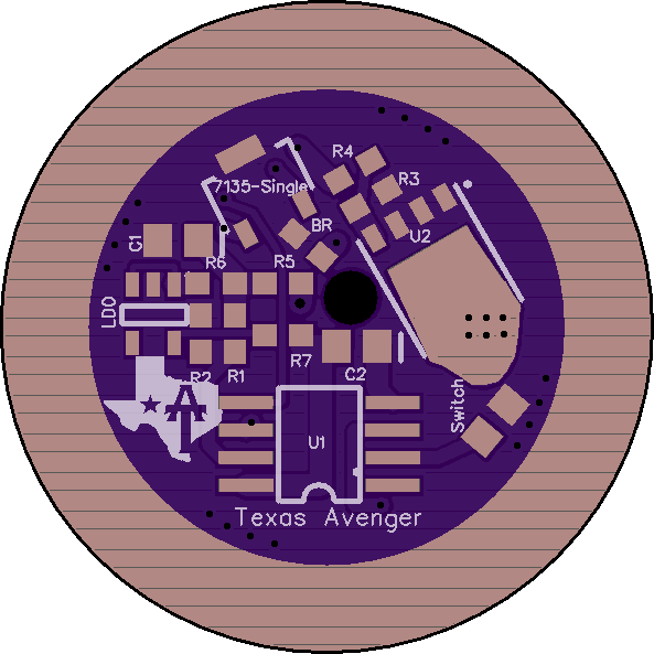
I have combined a 30mm TA LDO driver with a BLF Q8 switch. Does anyone know where I need to solder the white switch led wire to make the switch light up?
It should be on third pin of attiny, but this driver is adapted to work with 3 channels.
Do you have this driver?
Remember that you have to choose:
3 channels and a button without backlight
or
2 channels and a lighted button.
Yes, I have this driver. So with 3 channels there is no possibility to get the switch lighted?
You can just wire it up so the switch is always lit but it will not have LVP or be controlled by the driver, it will simply be on anytime there is a battery inserted.
That is fine for me. So I need to connect it to ground or to a positive contact?
Positive, gnd is common with the button.
So is it the left or the right leg of the 7135 or do I have to connect it to the spring pad?
I do not remember if there are any resistors on Q8 switch board. If yes than connect with spring pad (in the picture in blue)

You can have 3ch and aux LED control. Look at the pinout for the ROT66 driver to see which pin is what.
Hi BLF friends.
I modded my Haikelite MT01 with a TAD01 driver and a xhp50.2 3 volt emitter on a Noctigon 20mm mcpcb.
The original driver is about 40mm, and the TAD01 is 38,5mm, but it mounted in the light without any problem.
I used the original positive contact ring in the TAD01 driver, and it is a perfect fit.
Currently I’m using my custom compiled Narsil but I would like to try Andúril.
I understand that Andúril is a more complex firmware. Is there a Andúril hex file to download that is already compiled to run with TA drivers?
I searched BLF but couldn’t find it.
Appreciate any help.
Somehow I still haven’t given up yet… Hoping I could get some more help. I saw some of the tools people were using and thought surely those will make this possible but still no luck. I decided to back down to a FET+6+1 to keep things a little more simple til I get this going right but I have attached some pictures of the last two I’ve tried and hope you awesome bunch can help me figure out what my (i’m sure numerous) errors are. Please take a look and if you can offer some help it would be much appreciated. Thanks!


It actually doesn’t look that bad outside of excessive flux residue but I am sure you knew that.
Honestly I have had several drivers that I had strange issues with and just had to give up on them and build a new driver. Sometimes it is just not worth the hassle to troubleshoot a bad driver when it is quicker and easier to build a new one since they are so cheap.
Thanks! That flux is a real pain to get off of there, is there any trick to it? This is attempt number 5 and 6 actually, I figured I was messing something up with this part since I’ve never done it before. With you telling me they’re not so bad I’m starting to wonder if my ATTiny flashes may be the issue. I’ve tried many variants all on t25. I’ve tried the TA bistro, bistro, bistro tripledown and biscotti. If I pull a known good ATTiny off a convoy biscotti driver would it work on these for troubleshooting purposes or would it just not do anything?
It should work on here, just might not work “properly”. It should light up the LED on command though.
Strange you are having issues on that many drivers. It is possible your batch of PCB’s have an error someplace I suppose.
What was the issue again?
The only ones that have lit up for me have been full FET or off. Others won’t do anything at all. I got tired of building the flashlight every time and now run it through this hooked up to an led through alligator plugs.
It could very well be a flashing issue if it is not doing anything.
Thanks, that helps so much. I’ll narrow down on the flashing with the one that does nothing and hopefully things should get easier after that!
Technically you can probe the driver with a DMM to see if the MCU is working but it is complicated to explain if you don’t understand the driver setup.
You would want to check to see if there is any voltage on the MCU pins that go to the FET / 7135. This will tell you if the MCU is trying to turn them on.
If there is no output voltage then check the input power pins to the MCU to make sure it is getting power.