Yes this seems very cool
![]()
Any chance of releasing a BOM and PCB file?
To detail a bit more, the MP3431/32 can boost down to 0.8Vin, but it needs 2.7V for startup, and the Attiny1616 needs 1.8V, I believe that usually in AA drivers the MCU is powered by the always on LED boost converter that outputs a constant voltage below the LED Vf when the light is off, this means of course using a boost converter with low Vin and low voltage startup.
Here instead the necessary voltage for the MP3432 startup and the MCU is provided by another small boost converter.
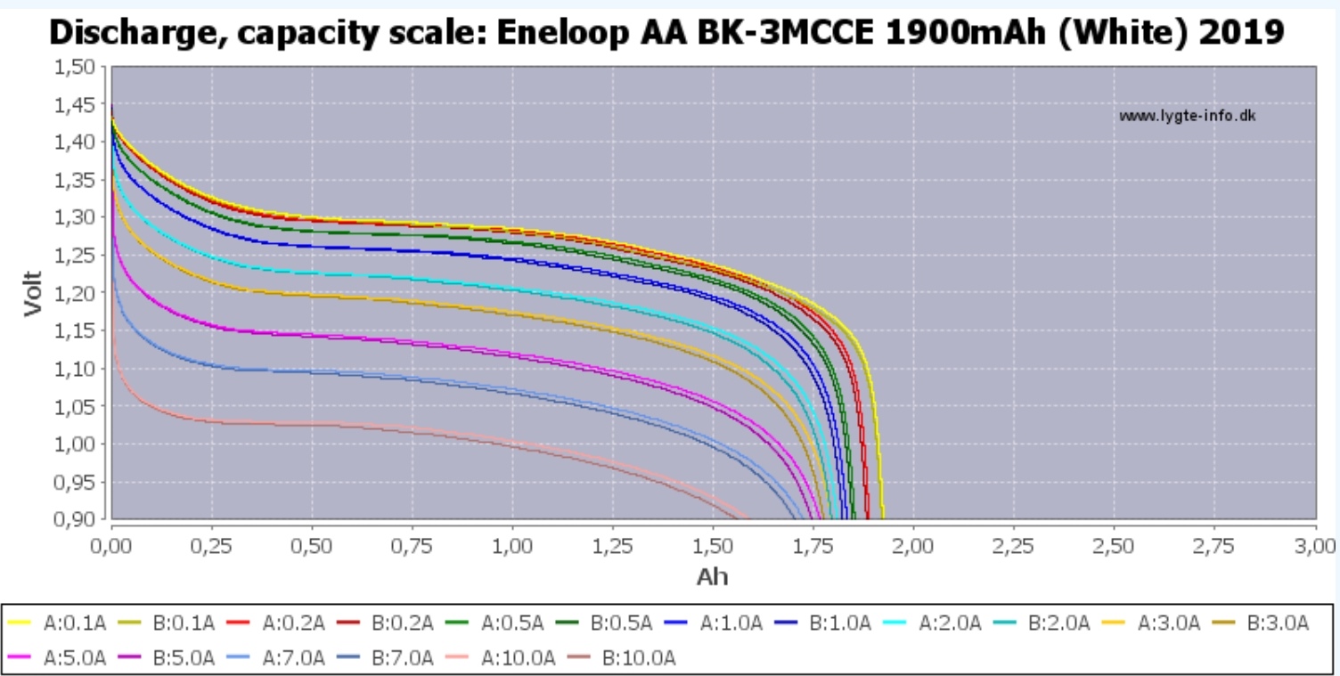
The advantage of using the MP3432 over the available low Vin boost ICs is that it has much better characteristics, the best low Vin boost IC available is probably the (very costly) LTC3425 used in the Zebralight SC5c, likely the most powerful and efficient AA light on the market, if we compare the internal FETs resistance it’s 40 and 50mΩ for the LTC3425 (equivalent 1 phase, because it has 4) vs 6 and 10mΩ for the MP3432, about 7~5times lower which help achieve much higher efficiency and power, although the limit here is the current deliverable by the AA cell, I haven’t tested yet with an Eneloop, only with my bench PSU. According to HKJ discharge curves, it should still be possible to pull quite a bit of current from it :
With the PSU there is a bit of funkyness at 1Aout, the efficiency is significantly lower and sometimes it would pulls very high current, very strange especially since the inductor saturation is higher than necessary, but I’ll see with an Eneloop.
The other advantage is that it has higher output voltage capability, low Vin boost IC usually have a maximum output voltage of ~5.5V, the MP3432 can output as high as 16V, the limitation is the maximum duty cycle, which should be around 93%, meaning 1/(1-0.93) = 14.2Vout at 1Vin, so it should be able to power any LED from 3V to 12V.
Because I wanted high efficiency for both chemistry I didn’t implement a linear regulation or FET PWM dimming when Vin>Vout, thus the big drawback is that it’s a boost only driver, if li-ion capability is desired then a 6V or higher LED must be used, here it is configured for 3S LEDs for the FWAA (I need to figure out how to modify the 3P original MCPCB). Options for a single LED light would be XHP50.3 HI, B35AM for 6V and XHP35 HI for 12V, which would maybe be more adequate for a small reflector and the usual 3535 MCPCB in 14500/AA lights.
The efficiency would probably break the 90% barrier at 1.2Vin 6Vout, and even better at 3Vout, also I had to use a 2mm tall inductor (XAL6020) for the FWAA shallow cavity, a 3mm inductor would be appreciably better, a XGL6020 would also have been better but they are only sold from Coilcraft direct (high shipping and duty fees), thankfully someone from the US will be able to reship some XGL inductors for me to test.
I’m sure you are taking this into consideration but for AA/NiMH lights I feel like standby drain is pretty important as lights with these batteries are good choices for emergency lights that sit for extended periods.
Yes I did think about it when designing but I forgot to check.
I just took a measurement and I get about 51uA at 1.2Vin.
Geesh! Good work, my man. Is there a way to work around the startup voltage?
One trick that the SP10 Pro employs… it uses a separate, small low-power boost chip just for running the MCU; then it shuts off the big boost chip when the light is off. That let’s it have a really low standby drain, though 51uA seems just fine to me.
Thanks.
Well it’s the same thing then, I have a small boost converter with 3V output powering the MCU and providing the sufficient voltage for the MP3432 startup.
So 51uA is the current draw of the small boost converter powering the (sleeping) MCU when off. *
Though if you saw my comment on the Anduril 2 thread the it’s possible I have a leaking pin and if I solve it the standby drain could be actually lower.
Edit : * and max 25uA (at 3Vin) from the MP3432 in standby according to the datasheet.
Well crap… I read right over and and missed that tidbit!
What’s the SP10 pro standby current ?
Edit :
Yeah, it wouldn’t work without it ![]()
I measured 40 uA on an Eneloop. SammysHP did a bit more scientific testing and saw 40-60 uA: Sofirn SP10 Pro (AA/14500/Andúril 2) - now available! - #1757 by SammysHP
So I’d say your results are right inline with the SP10 Pro. Not saying that’s perfect though. If you think it could/should be lower, I’d have to look again at the peripheral tables to see what is active in sleep mode and see if there is anything else that could be slowed down or shut off.
OK, so yeah it’s pretty good.
I took some quick standby measurements with aux LEDs at 1.2Vin :
AUX = 97uA Iin=380uA
AUX = 52uA Iin=220uA
AUX = 24uA Iin=126uA
I fixed the battlevel voltage divider issue I had by reflowing another T1616.
On less good news the input current at 60uA out is 11.5mA, which is certainly high, low modes won’t have long runtimes. Most of that power draw is from the MP3432 in Ultrasonic Mode (30kHz min), if it was in Pulse-Skip Mode it would consume much less, but it requires 2 more resistor and there is a risk for audible noise at low input which I don’t really want to take.
Also, the MP3432 powers itself from its output when its Vin pin is <3.3V (that is the case with the 3V small boost supply), so it boosts to the LED Vf (7.5~8V) then the internal LDO regulates that to 3.3V. It would be more efficient to use a e.g. 3.5V supply. Unfortunately the next available voltage for the small boost converter is 4.5V, a bit better than 7.5V but another thing to consider is that the MCU current draw increases with higher VCC… in the end I’m not sure much can be done about this low mode power consumption.
Edit : we can see it when increasing Vin from 3.3 to 3.4V, the input current drops from 4.7mA to 3.9mA, then it increases to 4.05mA ar 4.5Vin, so a 4.5V boost supply would be potentially a bit better than 3V.
To modify the FWAA MCPCB to 3S I cut two traces and reversed one LED :


Then it’s pretty much like my FWAA with buck driver mod :

As I mentionned in the Anduril2 thread the AUX LEDs don’t work with the lower nimh voltage range, so I cheated a bit for the video and swapped the batt voltage reading to VCC (=3V) so that they turn on at low Vin.

1 Thank
I just pushed a fix for this to my branch, rev 626. The only change is in aux-leds.c. I don’t have a test light for this, so if you would, give it a shot and let me know how it goes.
Nice
Another great development thefreeman!
Great work as always thefreeman :+1: . Will you share whole Kicad project?
I can’t understood why so great driver developers like you and loneoceans, if the your projects are truly OSHW and OSS why you not share all files like schematic and PCB files with BLF community, and not only firmware with PCB gerber?
In that case it is possible to everyone to make modification for example with cheaper or replacement components because now is shortage for so many electronic parts. I don’t want to offend you but I really didn’t understand reasons to not do that. Also it is possible to develop forge of your driver like without HD range. That can be made simple replacement of so many FET and linear drivers.
icpart, Really? You want whole project on plate ? ;))
Why not? If the main idea is to be in spirit of openness.
I think you have mentioned open source multiple times but I don’t think freeman has explicitly said it is. People seem to expect support also once things are made open especially while the parts are still yet unobtainable. Let him enjoy his hobby and lets not burn him out right away ![]() If he releases everything then so be it but if not it should not matter, he has not promised anything and owes us nothing.
If he releases everything then so be it but if not it should not matter, he has not promised anything and owes us nothing.
1 Thank