I modded my Q8 to not working status if that counts.
First attempt was 4x LH351D 80CRI 5000K I ordered from Digikey.
Keep in mind I have everything bypassed, new screws and had a ~7,000 lm Q8 with stock LEDs prior to this latest mod.
In mule form I tested it out with one battery, probably did the regulated channel it defaults to and everything seemed fine. Excited, I quickly finished putting everything back together and got the 30Q’s off the charger. I think it turned on somewhere around 3800lm (in turbo) if I recall and I instantly got the lovely blue LEDs. I look and I have 2 LEDs off, 1 LED barely on, and 1 LED “mostly” alive.
I thought maybe my reflow was bad because I just re-used the existing solder but even after re-doing it with more solder those 2 LEDs just didn’t want to work any more. Since I only bought four of the LEDs I had to improvise. I still have more LH351D 90CRI 4000K so how about some color mixing?
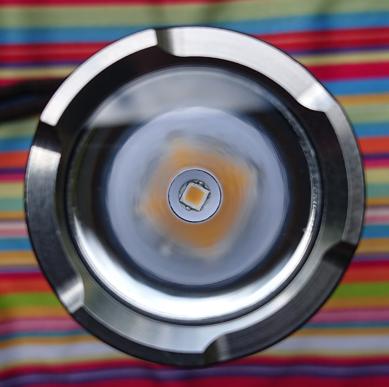
Here’s 2x 4000K 90CRI and 2x 5000K 80CRI (the damaged ones from round one):
The dirty LED on the bottom right is on but basically relegated to permanent moonlight.
—
A couple things I don’t understand that maybe someone could help me out with:
I’m guessing this is similar to the reports of other people killing single LH351’s in low resistance lights since it’s essentially giving one battery’s full current to each LED?
Why does the light not come on in moonlight anymore? It will only turn if I ramp up just above the regulated setting now. Is this because of that severely damaged LED, if so what is the technical reason?
I guess this isn’t worth trying a full set of 4000K 90CRI to replace the damaged ones, I assume those would just burn out too unless I undo my bypass…
I’m not claiming what I think is for sure what happened but the key may be in not using new solder when soldering the leds (if that is what I think I’m understanding) :
when removing the old leds half of the solder sticks behind on them leaving too little solder left on the board for the new leds
old solder does not contain flux anymore so the solder surfaces of the new leds were not wetted by flux causing solder to stick less well, leaving (partly) cold solder joints.
So with the solder pads not fully joint with the board the leds have a severe heat shedding problem and can turn blue and die.
And once the led with the worst solder joint goes, the 4 batteries in parallel work on 3 leds instead of 4 which increases the current per led so then the next baddest one goes etc.
These leds do survive direct drive on one high drain cell (the ones tested at least did, you never know if they all behave the same since we are exclusively working out of specs here on BLF ) , but it is kind of harsh on them if they are fed with multiple high drain 18650’s parallel (which provide higher voltage/more current).
I’ll have to replace the two bad ones and try again then. Is that bad LED just creating a ton of resistance making the lowest modes not work right or what do you think causes that?
I didn’t get many pics but I did another boxmod errr… mod :sunglasses: This one has runtime plus
I wanted to change the resistor on the LD2 driver to change the max current but the parts are so small and I can’t solder small so I just left it. As a result it is WAAY over powered for this light. Low is really the main usable level.
To investigate what is causing the low efficiency, of this sliced LH351D, today I sliced the dome of the LH35D1 4000K 90CRI led in my Sofirn SP33 (that had no other mods than a led swap, edit: not true, I lowered the current limiting resistor in the driver), but I recorded the numbers before and after the slicing. The slicing went exactly as my last one so a pretty perfect looking result on the outside.
Here are the before-after results:
Keeppower 6000mAh———4.13 V————4.13 V
Current at high 5———3.73 A————3.73 A
Light level 1—————18 lm————15 lm
Licht level 2—————56 lm————46 lm
Licht level 3—————204 lm————165 lm
Light level 4—————495 lm————403 lm
Light level 5—————960 lm————785 lm
Throw (measured@7m)——17.2 kcd———25.6 kcd
So there you go, 18% light loss from the procedure, which is more than with a classic Cree dedome (~10% if done well). Adding the lower bin of the high CRI led to the loss by slicing it, you get pretty close to the 50% efficiency loss compared to the 70 CRI LH351D.
Do I think with this new knowledge that slicing the 4000K 90CRI LH351D was worth it in the SP33?, well, by just: the 18% light loss for me is about compensated by the considerably better tint and added 50% of throw.
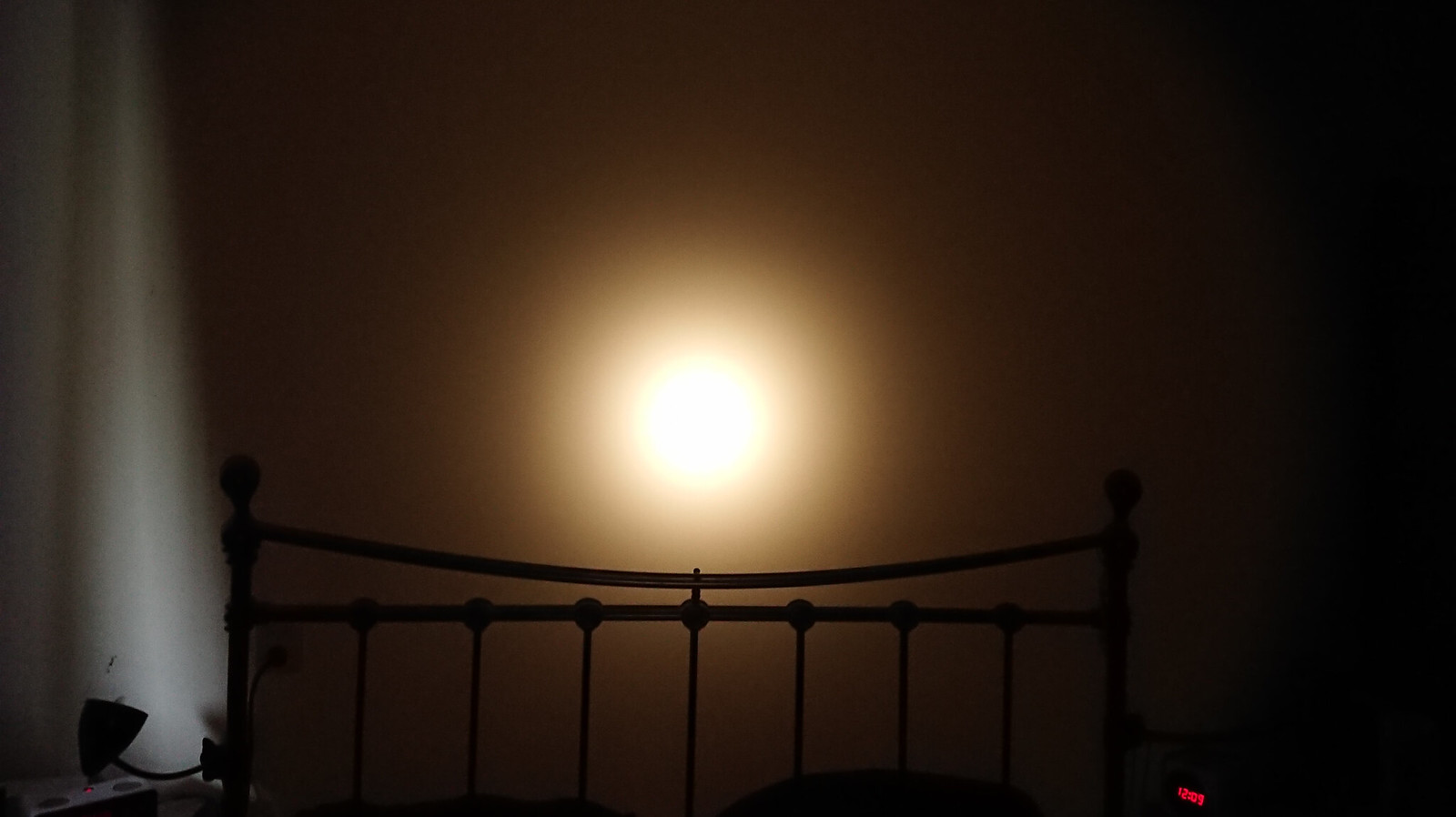
Btw, I sanded the underside of the centerpiece thinner to adapt the focus for the dedomed led and the beam is beyond perfect now:
I can’t.
I already included 10% dedome loss in the numbers above. Going up to 18, you should expect 58-68 of TA number. I think we can even say 18.5% based on your SP33 measurements, that brings us to 58-67% of TA number.
As you indicated, your sphere may be more pessimistic than his, this may be a part of the explanation.
You assumed 18% optical losses…which looks too high for me for optics alone (I would say 16-17% with uncoated lens), but after adding bezel losses maybe it’s slightly too low?
Throw increase is a bit better than my calculations show, with 18.5% output loss I would predict 40% and you got 49%. But my intensity estimations for the domed variant were not very accurate, I guess that may be the reason.
You have quite a will to catch everything in precise numbers, please carry on with that! But I think that many of these parameters have more variance than you want them to have. To give one example, I suspect quite a variation in reflector reflectivity around.
Agree, that is really cool. But what is a boxmod? Is that a vaping thing and you have made the copper stuff to make it into a flashlight? (if so, it is even more :sunglasses: )
Yeah I think that’s the idea, I’ve been looking at some of those vaping devices as hosts, some nice copper single tube ones.
I thought PP had some new CF Spy 007 at first glance there.
Well, I believe that every practical result that we see can be explained by theory.
If we do calculations, at every step take the most pessimistic value and still arrive with results that are too good - we miss something important.
In general, the number of variables which are hard to account for in this type of calculations is huge. Especially for those of us who lack CADs capable of doing optical simulation.
For this reason every such calculation must be sketchy.
In the past month I did a lot of calculations of performance for A-lights which I proposed as future BLF projects
My goal was to get within 15% of actual performance. I quickly realized that I just can’t do this. I went on anyway trying to simply do my best. In a way, I’m testing and refining my calculators now.
You suggested reflector reflectivity. Maybe, IDK what is the worst-case value for used but not damaged unprotected alu reflector.
I can add heat as unaccounted effect too, though a small one. CRI70 at this current is 22% efficient, generating 19W of heat. Your is 11% efficient, generating 21.7W of heat. (I assume Vf is the same…but high current suggests yours might be lower). Though LH351D has extremely low thermal resistance, that’s just 6 °C difference on the junction. Probably larger on the phosphor, which is probably thicker and generates higher losses. And you indicated that you use too much solder sometimes. Anyway, that’s probably less than 1%.
But I think I have a better explanation:
You have uncoated sapphire lens, right?
Uncoated sapphire transmissivity is low, 83-84%:
I never bothered to look up the transmission curve for sapphire, thought it would be close enough to glass or even better but wow, that stuff eats up a lot of light! In my S2+EDC the lens is 2mm, so that is 31% :person_facepalming: I will have a check though in my sphere.
But the order for a Sapphire lens for the SP33 went wrong so this one still has glass.
Not much different from 1mm (at least in the visible range). Which would indicate that the reason for low transmission is reflection. Though from this reflection would be ~9.5% (taking into account 2 sides).
Some checks, I measured output of my S2+EDC on lowest (constant regulated) mode, with 2mm ‘Sapphire’ lens, with 2mm uncoated glass lens, and without lens (lens replaced with o-ring to keep the reflector at about the same position from the bezel)
Based on these measurements I put sapphire between quotation marks because although I bought it as sapphire, you never know what you buy in reality in China. The lens does have a very shiny finish on the side that I have not seen with any glass lens before, plus water drops adhere less well to it than on plain glass. It may be hardened mineral glass though, who knows…