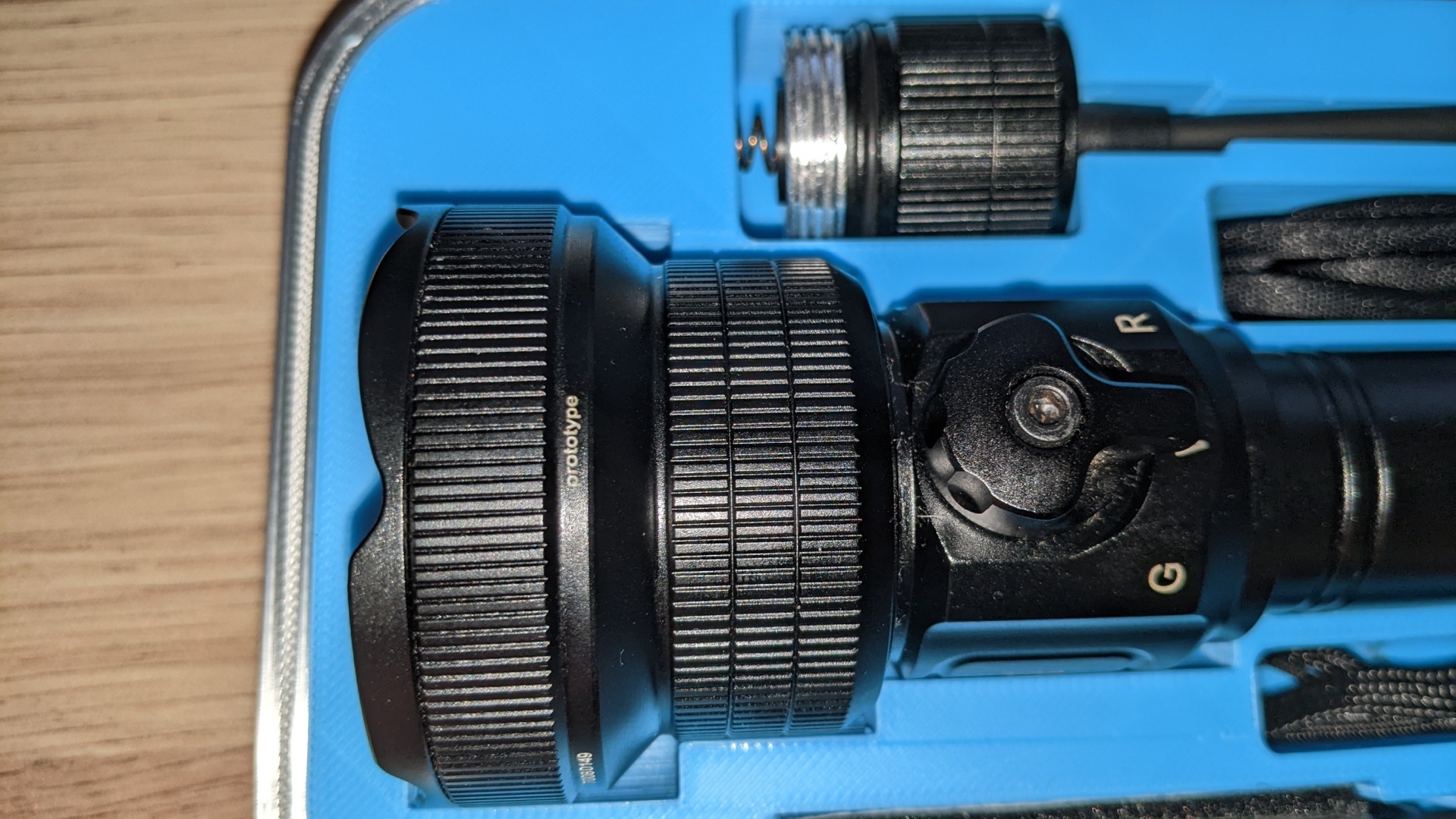
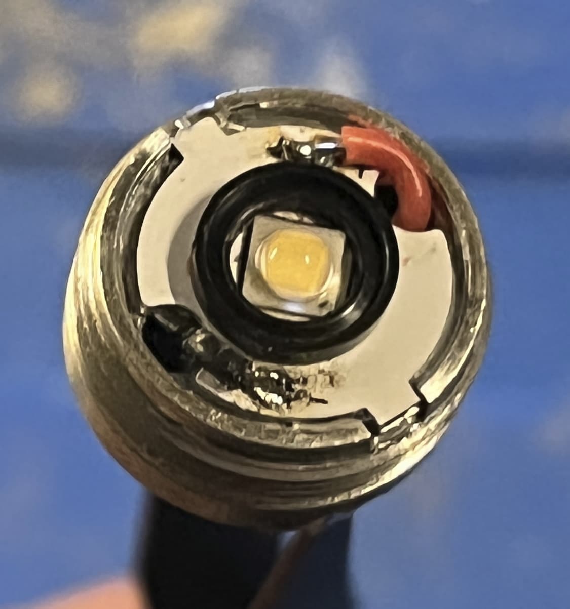
I am not really sure how this one is built, I think it is separated by an alu wall with just holes for the wires in, yes. So the Alu the led is mounted on is one piece with the head.
There is other designs such as Convoy S2+ where the entire flashlight is just a “tube” and the led and driver are attached to the same threaded brass pill, which is then screwed into the tube.
In theory 2 screws would be better, but the thermal paste seems to be a petty hard type, that eventually hardens and “glues” the PCB in place. In addition, the TIR is pushed down onto the led by the bezel, so it makes additional pressure.
Some lights like S2+ do not use any screws for the LED at all - just the mounting pressure from the lens keeping them in place.
The “wall” is known as a “shelf.” As @ebastler mentioned, the other common way to design a flashlight uses a “pill.”
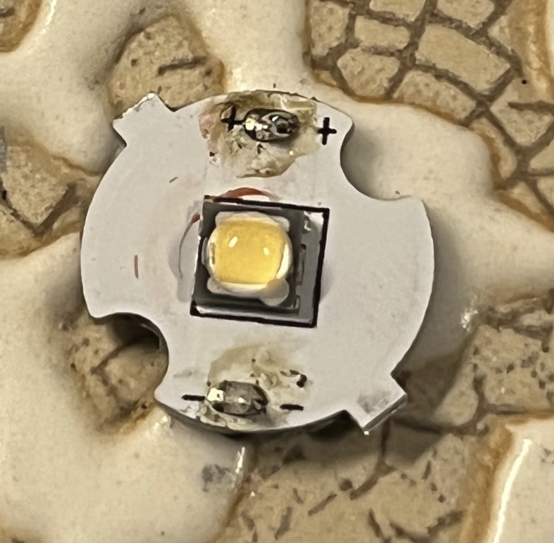
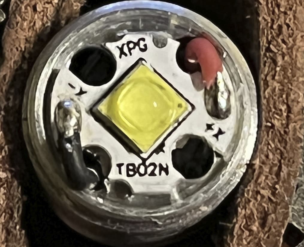
If you’re interested in swapping LEDs on this light, keep in mind the stock MCPCB (aka “star”) has three holes in it for the TIR legs, which is an umcommon design so you probably won’t be able to purchase a new MCPCB with the holes already made.
This means if you want to swap LEDs, the easiest thing to do is reflow a new 5050 footprint LED on the stock board. If you want a different footprint, you can use a 20mm MCPCB and either drill holes in it for the legs, or sand off the legs so the TIR sits directly on the MCPCB. (Some additional shaving of the MCPCB is also required if using a new 20mm one).
I recently did the method with drilling holes and put an Osram W2 Green emitter in mine (3030 footprint).
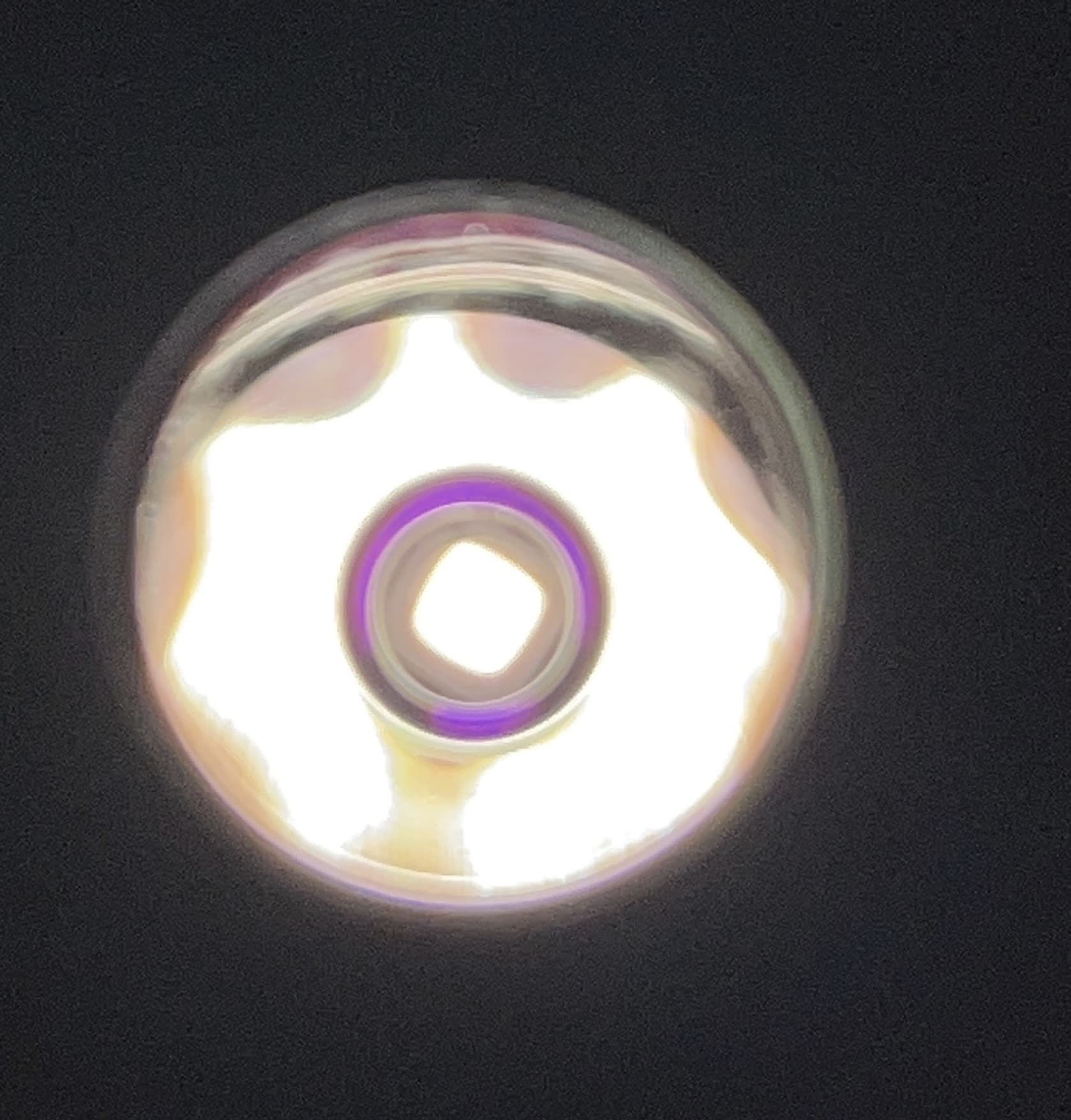
I’m not surprised adding aluminum tape inside a TIR housing didn’t do much.
What is the efficiency of a TIR? Something like 80-85%?
So figure 15-20% of the LED’s output doesn’t go into the beam.
But not all of that amount passes through the sides of the TIR to hit the inside of the housing. Some is absorbed by the PMMA optical acrylic as it passes through.
Aluminum tape itself isn’t fully efficient either. Some light is absorbed by the tape.
Any light reflected by the aluminum then has to pass through the PMMA to get out. Some will be reflected back into the housing, some will be absorbed by the acrylic.
Any light that does make it out will be scattered very widely in a hemisphere. Some in the beam, some in the spill.
To see a noticeable increase in brightness typically requires at least 20% more light. In this case the extra increase is probably only a few %. Because the amount of extra light reflected is so small this isn’t noticeable in the beam, but artifacts generated by it may be visible in dimmer parts of the spill.
Here’s my triple SP40. I did this mod quite a while ago, but I never shared it or took any pics. @INeedMoreLumens had asked me for some pics in another thread, so here it is.
I used a KD mcpcb sanded down, 4500K 519A leds, 10508 optic and 1/8" aluminum spacer. I had to make the spacer U shaped for room to route the wires since there’s a pcb right behind the shelf. I had to remove the driver to solder longer wires. I also ground away a bit around the legs of the TIR, but I don’t think that was necessary.
That’s awesome. Thinking of buying a couple of those drivers and an extra D10 and modding it. I have an early D10 clone from Amazon ‘Slonik’ and really like it, but modded it to sst40 5000k (form xp-g2) and cleaned the led shelf. Stock driver, but wish it had more output and better performance. Was it hard to fit that driver? How did you get the cover for the tail switch off? Reverse threaded?
There are a couple of nubs on the sides of the driver that need to be sanded off, and whichever edge where you choose to slip the wires over needs to be sanded down, basically enough so that the wires will fit between the edge of the driver and the host tube. I don’t have the light on me but I can take a photo later.
The tailcap is reverse threaded. Just use some needle nose pliers or stiff tweezers to unscrew.
Also the inside of the Jet-u, everything was incredibly small. The MCPCB was so light that I had to hold it to the hotplate when taking the emitter off, or surface tension would just lift it off. It was sold as XP-G2 but it looks more like it came with an XP-G3, was very cool white and low CRI.
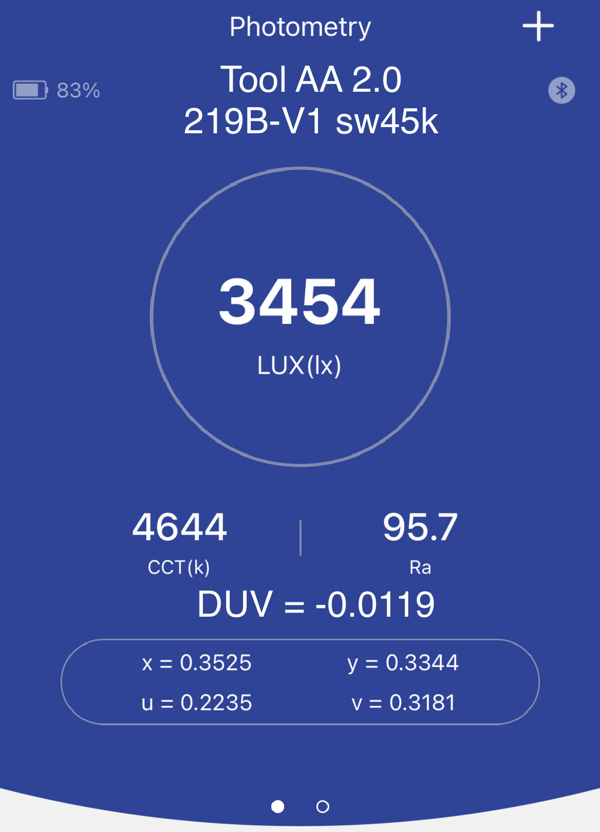
Unfortunately no other pics as I forgot to take more, though I can report it resulted in 1.6kcd, 4372k, CRI of 95 and a DUV of -0.0109, when using the high mode with a Vapcell 10440. Beam profile was similar to the Emisar KC1 with dedomed 519a sm573
If it wasn’t so fiddly to reassemble, I would post more pics, but it isn’t anything notable other than extremely small.
Did these mods a couple weeks ago and intended to post, but never got around to it.
Continuing my obsession with the FW3A, this is my second FW3A Lume1 + AUX upgrade.
My favourite EDC hanklight is an aluminium KR4 with 4500K dedomed 519As and a boost driver. With this FW3A mod, I wanted to upgrade an aluminium FW3A to equal these features and give me a modern FW3A for EDC. Therefore, this one also had to have 4500K dedomed 519As. The Lume1 driver was sourced from an FW3X and upgraded to Anduril 2. Only thing missing, from my point of view, is a stainless steel bezel. As soon as I get my hands on one, I’ll be adding it.
I love the size and weight of the FW3A and having one with my favourite 519As, AUX and an efficient driver puts it solidly back in my pocket for EDC.
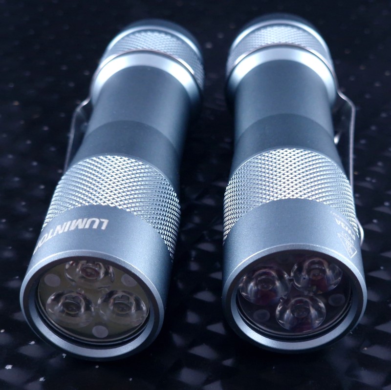
I chose a grey FW3A host to match the grey 1+7+FET Anduril 1 light I already have. The photos show both - oldskool and newskool together.
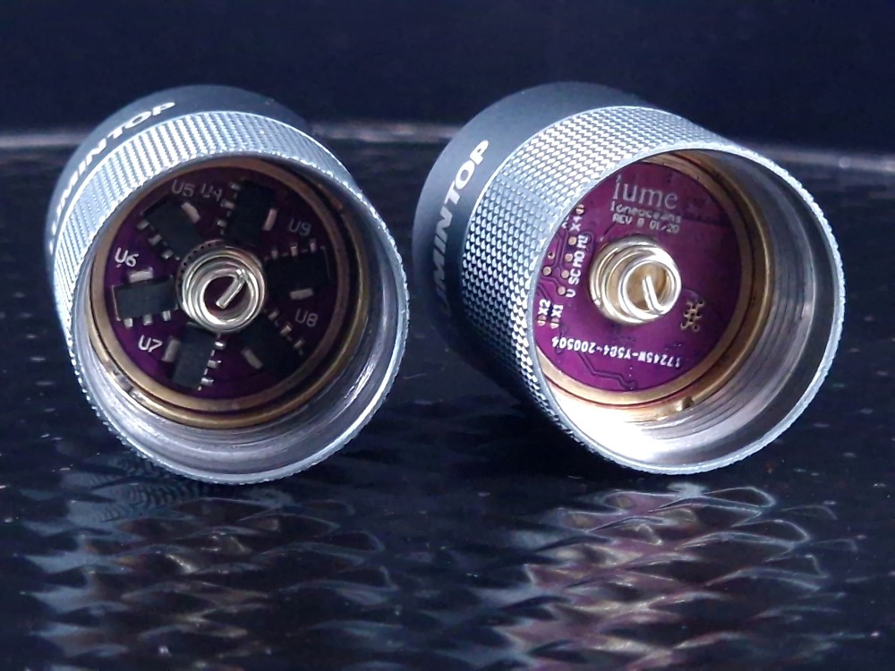
The only way to tell these two apart when they’re off is by looking closely and noticing that one has a glow gasket and the other has an AUX board behind the optic:
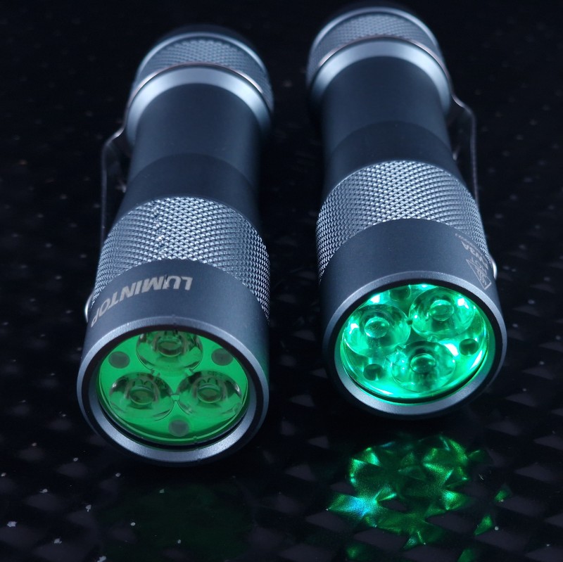
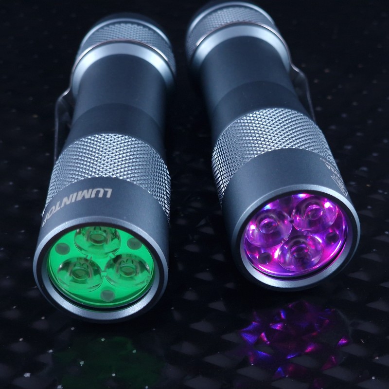
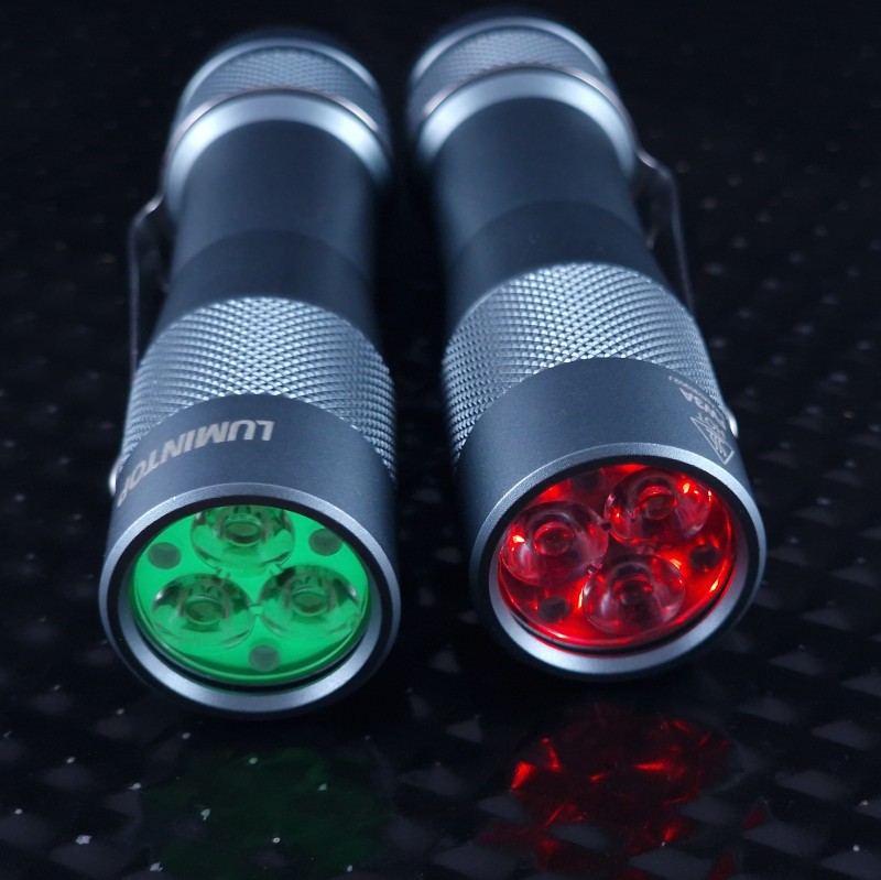
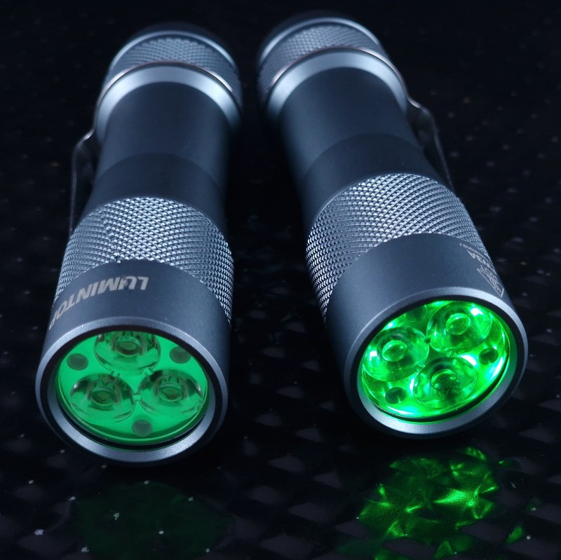
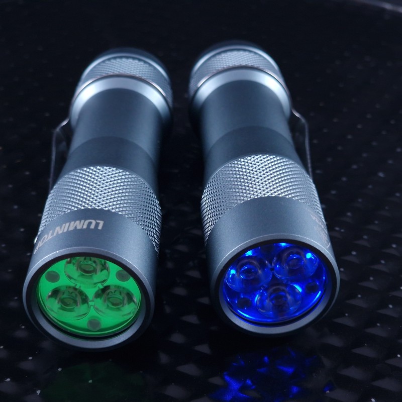
When the AUX are on, it’s easy to tell the difference. In this photo, the AUX lights are a green+blue mix, although with the default resistors on the AUX board, it’s closer to being green than being cyan:
I had a bunch of these Charger circuit boards from Ring battery packs – I finally got around to building a portable charger similar to the Olight version — I want to do something different with the magnet ends, they are just soldered for now ( soldering reduces the magnet strength) – I saw a video where the guy used spade connectors and just slid the magnets inside them