What did you mod today?

This just convinces me more that there needs to be more enthusiast focused headlamps with centered reflectors. I’m not a fan of right angle lights, the offset beam annoys me.

A lightweight 14500 cell D10 with anduril2 and regulated driver would be my grail light.

1 Thank

A D10 is not that heavy even with a 18650 cell. It’s driver can be swapped to a Convoy S21E driver which has Andruil 2 and boost versions but not together. The emitter and optic can be swapped at will. It’s the best diy headlamp.

There’s no reason why there couldn’t be an emitter or reflector swappable AA sized D10 either. It just takes the right manufacturer to do it. You don’t have to preach to me about the D10, I have 5 of them!

I’m using Autodesk Fusion in the free hobbyist license. I tried getting my head around freecad more than once but just couldn’t get anywhere near as efficient as my Fusion workflow.

1 Thank

For me personally 900mAh vs 3400mAh there is no comparison. I will pick the larger cell every time. It’s just the D10 is already a very light headlamp compared to most of other models on the market.

1 Thank

For me anything I wanna wear for an extended amount of time needs to have the battery pack on the back of my head.

I’m probably going to attmpt this with a resin printer for my spare D4K head but because the thread depth is so shallow I don’t think a test print with an FDM would even fit.

Also means I can have a back mounted cell holder, should work really well with the boost driver.

3 Thanks

It’s too big for my edc pack. Pretty much no 18650 lamp is small enough, except for maybe some zebralights. Light as the D10 is, I still feel it when I put it in my pack.

Compared to my manker e02 and e03 - those absolutely disappear in a pack. Too bad they’re right angle, and not anduril2. I can live with the decreased battery life.

1 Thank

Thanks folks! I know its rough, but for the form factor I wanted I couldn’t think of an Easy way to hide contacts and wires. Just wanted to know it would work, and just happy it does. I might try a redo a bit more streamlined, again as a modeling challenge more than caring to need it.

Would help if I was willing to drill side holes in the body, but I’m not. I want the mod reversible. I MIGHT look at an all printed battery tube, and channels for wires if it looks like this will get much actual use… my usual uses will wreak havoc with exposed wires.( Not to mention shorting out makes this a pipe bomb with the 14500 in it.)

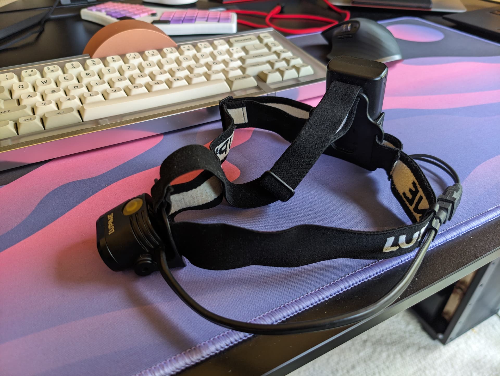
@darosk indeed, that was part of my reason to try. The simple way to use this light as a headlamp is the old school bit of just putting it on the side of your head above the ear. but I always hated that for activating, adjusting, weight balance, and offset light… basically everything.

I had thought last year that I’d hate the off center of an angle light, but so far with a HD15 it hasn’t bothered much. I did adjust it further off actual center, to center the emitter more in a custom Headlamp mount I did though… it is nicer!

I could have also went with battery pack elsewhere, but I’ve never like the wires or bulk associated with behind the head battery packs. I like to be able to lay my head down if I’m wearing one of these under something, like a house or car, which is common. Figured if I was going to prove a concept, I might as well do it within my own usage preferences.

@James_C I’m using OpenSCAD. Which is if you say rabbit hole for freecad, is a deep dive into a kangaroo den… lol.

OSCAD is a programmer’s modeling software; it uses a text based programming language to describe the model. And it is old school solid modeling, not a “modern” mesh modeler.

Perfect for me, I find I have more control than point and click software, but it is generally slower, and most folk even die hard computer geeks will think its pointless to model this way. But I started modeling with something extremely similar for 3d graphics rendering several years ago(26 years! yikes I’m old), (called POV-ray), so this is right up my alley.

One more of mine , couple months ago actually, my only real mod directly to a light… well, a replacement part on a light.

Found the shoulder clearance on Convoy 18350 tubes are too short for some Wurrkos lights, so I deepened(smaller dia) the one that was there a touch, then made it longer. This is rather easy since I just happen to have my own metal lathe. (A decade ago I was making my own brass bodies for some of my lights, when that was just starting to be a “thing”, will have to post pics of those if I remember to…)

Also added an extremely shallow chamfer to the new edge into the knurling.

And with a HD15 head on it, thd ond I currently use it with, bottomed out.

6 Thanks

I agree, horrible solution. A while ago (8+years) there used to be a ?niteize headband with an ‘over the top’ strap which had a loop to hold a light, I’ve never tried this solution, I worry it’ll sit too high on your head, and will possibly flop around side-to-side because the elastic isn’t rigid to torsion.

One of my projects currnetly on the list (waiting for life to get less busy), is modding an Emisar DW4 18350 tube to take an external battery (back of head or belt mount). Using the Skilhunt HB3 headband and the Tactical Grizzly 3D printed clip, this should reduce the weight and the light offset.

1 Thank

This is peak headlamp shape to me. Their UI however is terrible, and mine is pretty ancient and has (by today’s standards) bad LEDs. Wanted to replace them with something more modern for a while now…


Oh and Lupine is definitely not BLF friendly :sweat_smile:

1 Thank

Not budget friendly, but I do admire their designs. Remote battery packs seem like they are not that popular, especially on this forum, I can see the drawbacks- as AK-Adventurist says, having the battery on the back of your head makes it hard to lie your head on the ground. Cables also are invariably a source of weakness.

That said, belt mounted headlamp batteries have been used for many decades in mining lamps, where reliability and long runtime (12hours) are required; it’s only fairly recently ( last 7 years or so) that LED and battery technology has allowed the development of self contained ‘caplamps’ to be certified and available.

2 Thanks

As prompted by @mcjtom I tried adding alu tape to the head of my IF19:

Did not change much regarding beam profile or brightness… Don’t have any good pics, but not much difference imo (left is before, right after).

However it did add some weird petal-shapes to the spill, probably where the light reflected by the alu tape is getting back into the TIR, through the 3 “legs” of the TIR. Rotated the light a little between the camer so you can see them moving along with the light:

Bottom line: Would not recommend doing this on a IF19.

6 Thanks

Swapped a 519a 5700K DD into my i3E EOS.

The stock LED footprint was sepcial (iirc it’s a 3838 plastic package LED) and required some modding to fit a standard 3535. Not recommended as it was such a hassle to get to work.

So to modify this, I scraped away some soldermask around the isolated thermal plane, which would short to the upper cathode trace. In order to not short the driver out, the longer anode trace was cut close to the via and soldermask removed.

Both traces now did not have an electrical connection to the LED. To solve this I cut some 3.5x2mm pieces of copper out of 0.1mm copper shim to bridge the gaps. They were tinned beforehand and loosely attached to the board using some sticky flux.

It turns out an iron at 320° is enough to heat the whole LED through the sapphire substrate so all I needed to do was hold it down with tweezers and heat the portion of the shim that stuck out.

I may have forgotten to take beamshots so I will hopufully update this evening, the beam is slightly off-centre if viewed point blank ahd has a few artefacts due to it being a fully smooth TIR. It is predictably a bit floodier and much more neutral tint with a dedomed 519a. R9080 is also a bonus

14 Thanks

I finally finished my FWAA mods!

Baked (I had some issues after baking…), T1616 MCU Upgrade, 519A 5000K and RGB Aux!

Big thanks goes out to @gchart(original T85 to T1616 Adapter), @Adair21(RGB T85 to T1616 Adapter), @thefreeman(FWAA Flex Aux PCB), @ToyKeeper(Anduril)!

Link to my FWAA T85 to T1616 PCB on Oshpark:
https://oshpark.com/profiles/INeedMoreLumens

Note: The Adapter will only work on driver version v1.1, it will not work on v2.2.

Link to T1616 MCU on Digikey:
https://www.digikey.com/en/products/detail/microchip-technology/ATTINY1616-MFR/7354617

14 Thanks

Fantastic!

1 Thank

Thank you, of course, for doing it. I’m learning, and hence another question looking at your pictures. It looks like the (I’m not sure what it’s called - a star or a PCB board with the LED on it?) is attached to the rest of the flashlight with only one screw? Is that correct? It seems that there is a place for the second screw? Wouldn’t it be better, heat management-wise, if the back of the star was more firmly touching whatever works as the heat sink?

And on the latter: is the housing of the flashlight divided by an aluminum ‘wall’ between the head and the driver/battery compartment? Or, in other words, what is the ‘star’ attached to, or how does the heat leaves the LED?

I’m sorry for the questions - I will get this light soon, I’m just curious.

Thanks!

1 Thank

I am not really sure how this one is built, I think it is separated by an alu wall with just holes for the wires in, yes. So the Alu the led is mounted on is one piece with the head.

There is other designs such as Convoy S2+ where the entire flashlight is just a “tube” and the led and driver are attached to the same threaded brass pill, which is then screwed into the tube.

In theory 2 screws would be better, but the thermal paste seems to be a petty hard type, that eventually hardens and “glues” the PCB in place. In addition, the TIR is pushed down onto the led by the bezel, so it makes additional pressure.

Some lights like S2+ do not use any screws for the LED at all - just the mounting pressure from the lens keeping them in place.

2 Thanks

The “wall” is known as a “shelf.” As @ebastler mentioned, the other common way to design a flashlight uses a “pill.”

If you’re interested in swapping LEDs on this light, keep in mind the stock MCPCB (aka “star”) has three holes in it for the TIR legs, which is an umcommon design so you probably won’t be able to purchase a new MCPCB with the holes already made.

This means if you want to swap LEDs, the easiest thing to do is reflow a new 5050 footprint LED on the stock board. If you want a different footprint, you can use a 20mm MCPCB and either drill holes in it for the legs, or sand off the legs so the TIR sits directly on the MCPCB. (Some additional shaving of the MCPCB is also required if using a new 20mm one).

I recently did the method with drilling holes and put an Osram W2 Green emitter in mine (3030 footprint).

2 Thanks