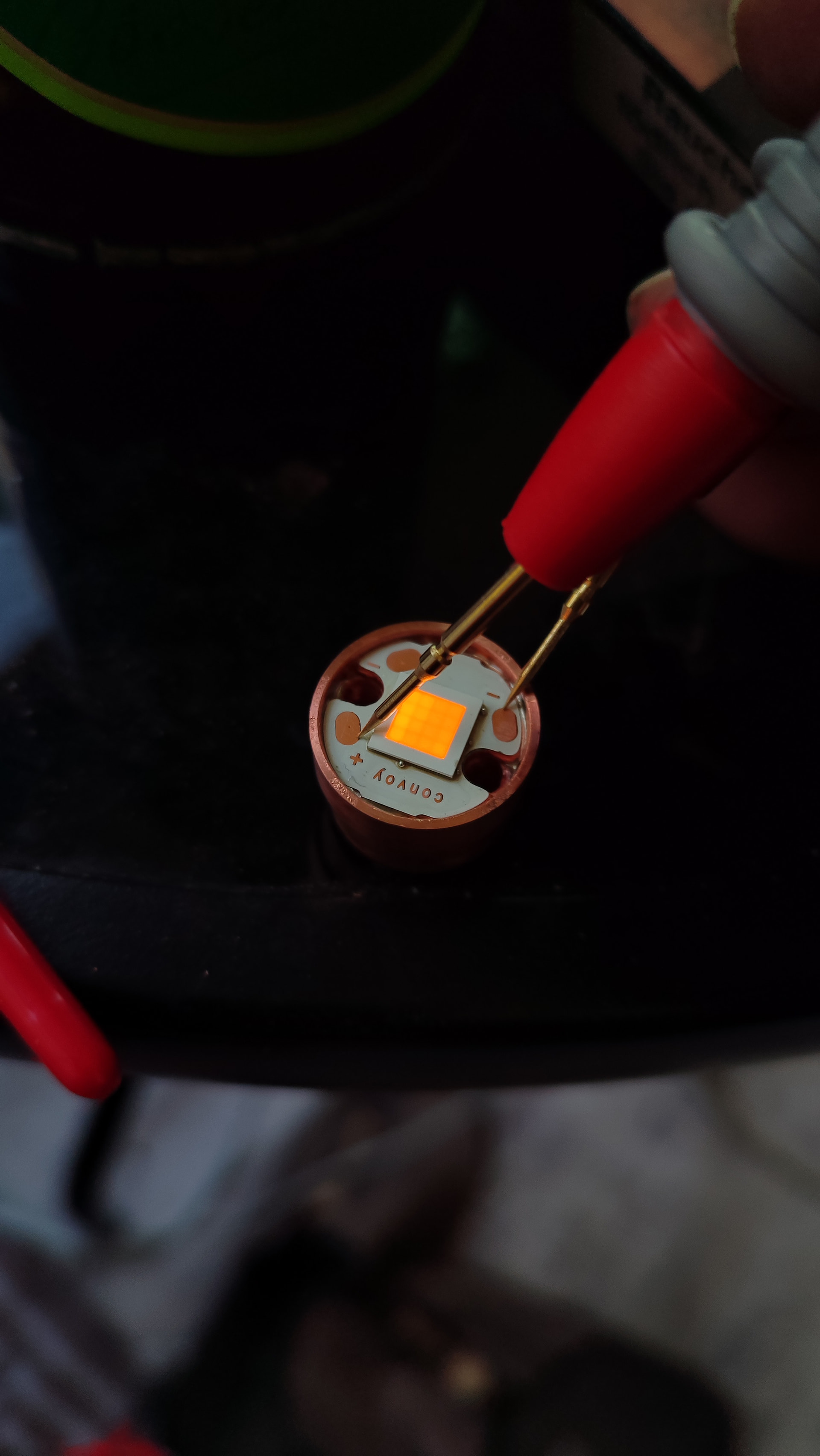
About 10A of it ![]()
The battery’s not gonna be happy but what the hell. I’ll just skip all the bypasse and probably still get 8A at the led ![]()
About 10A of it ![]()
The battery’s not gonna be happy but what the hell. I’ll just skip all the bypasse and probably still get 8A at the led ![]()
Nice!
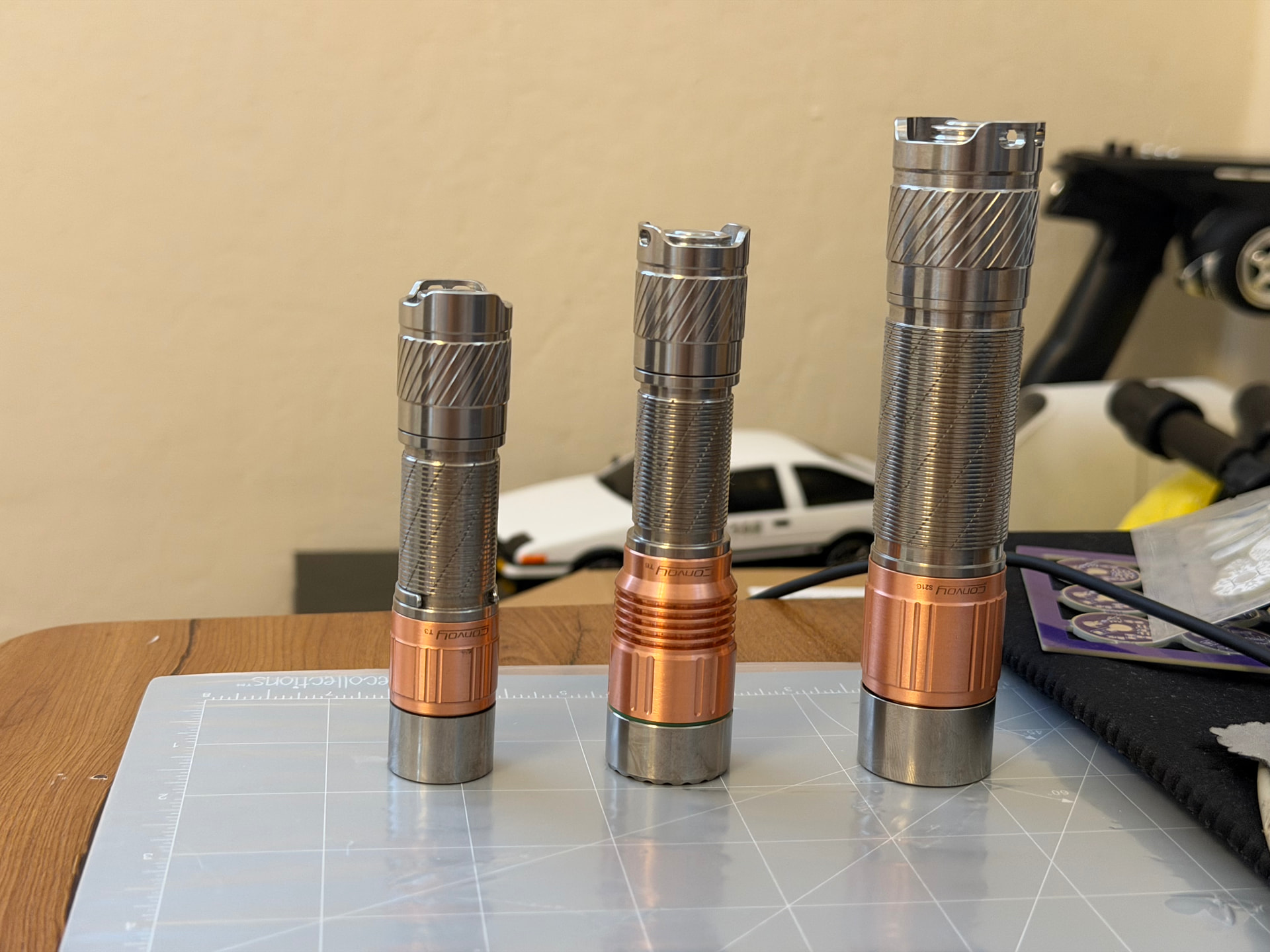
Nice! I kinda envy of those nice smooth mules!
Is it a lhp531? The perfect match for a T3, insane amount of light for the size!
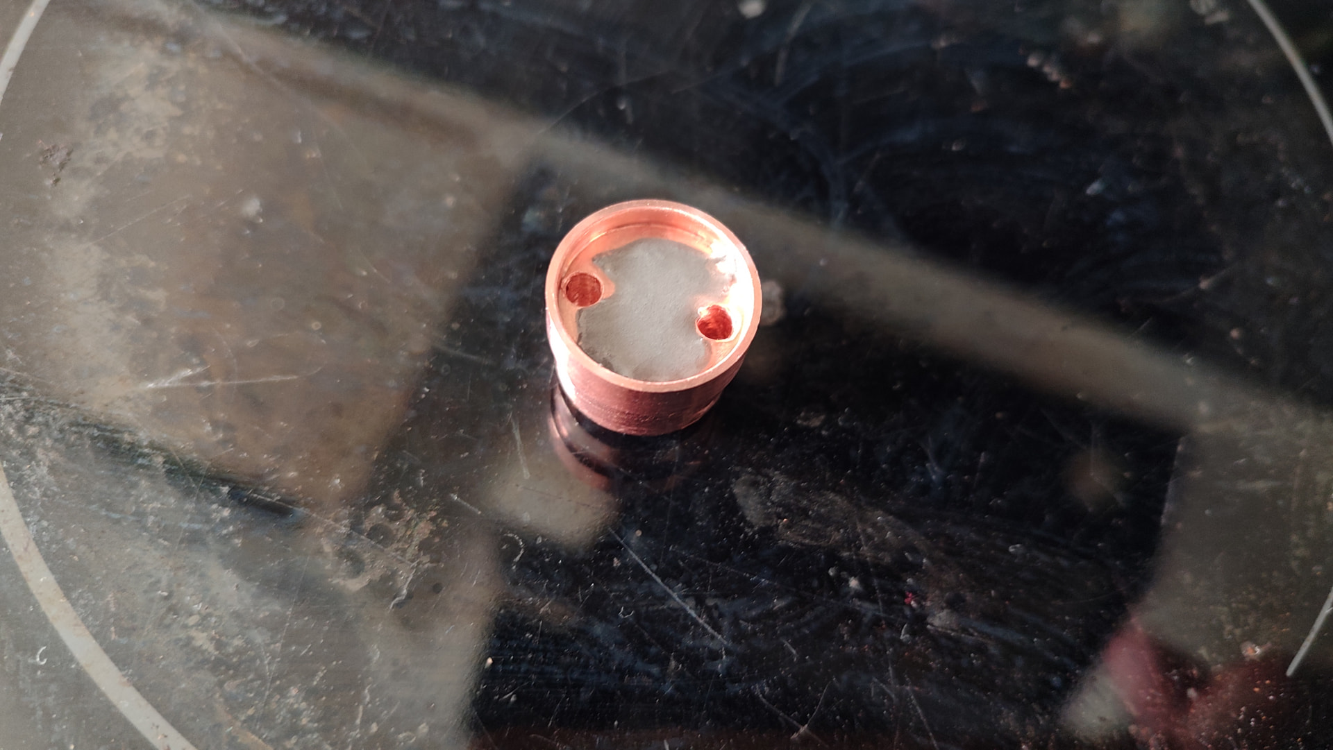
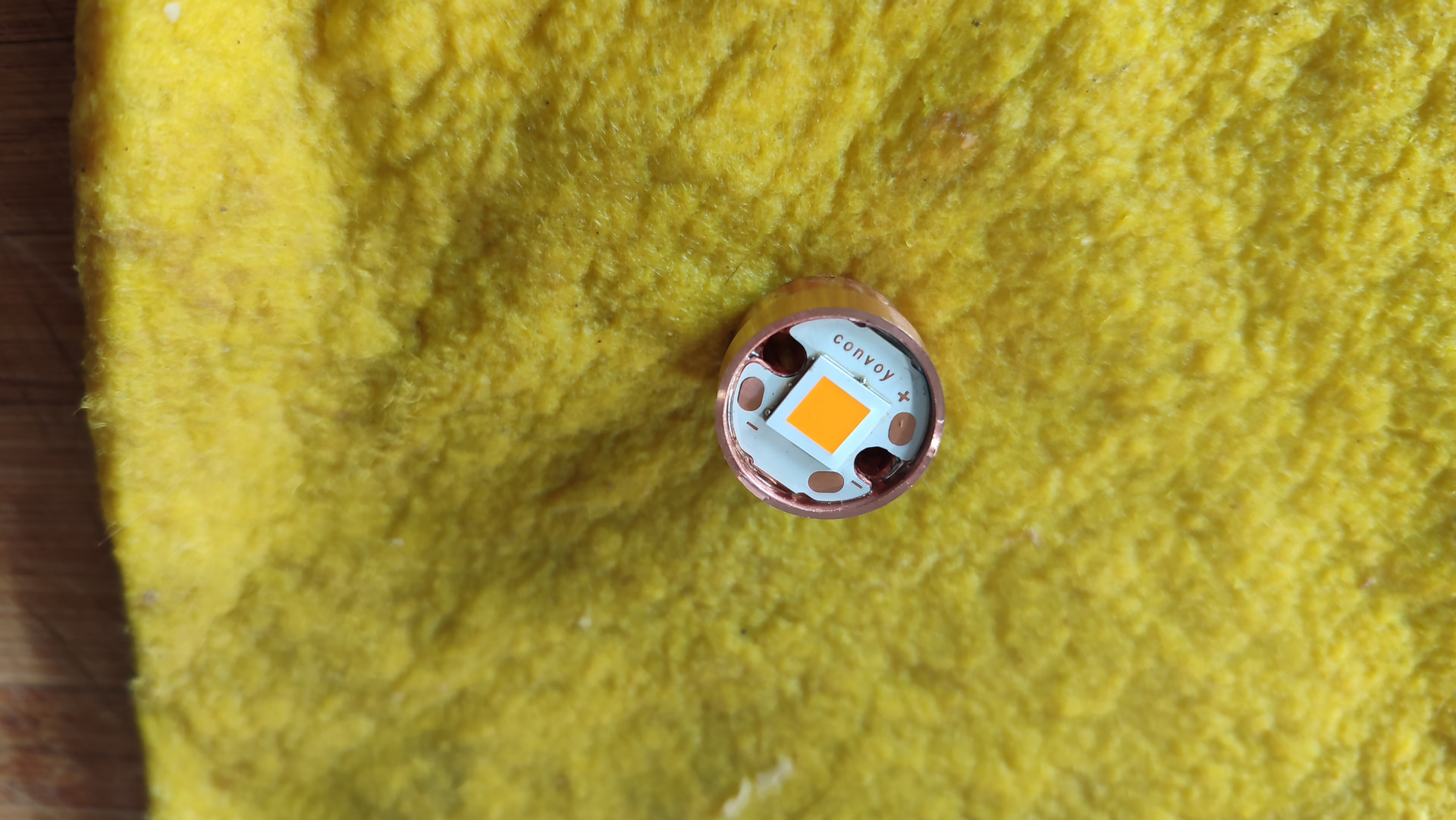
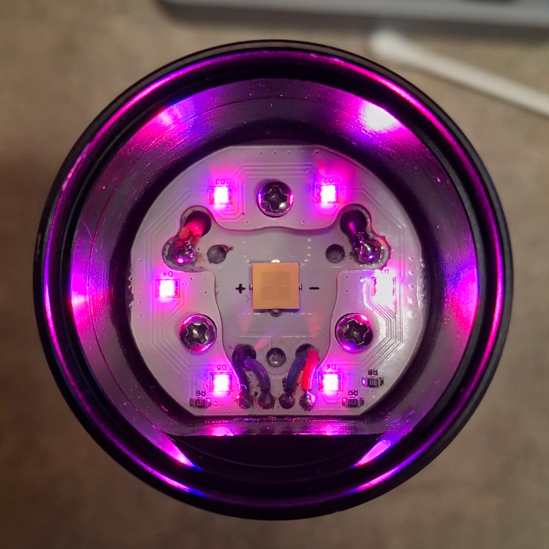
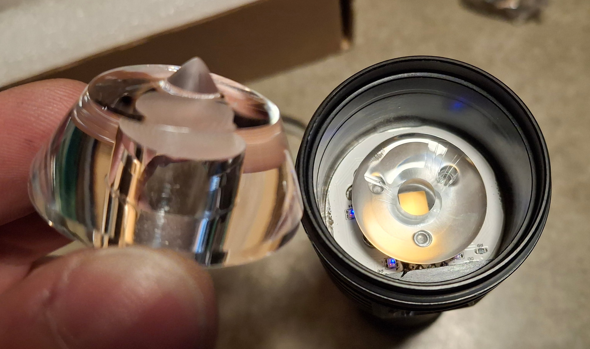
The first photo is funny, I thought the emitter was floating very distant from the MCPCB, but that was just the top silicone layer ![]()
How do you keep the MCPCB in contact with the mule?
I used a very tight fit on the cooper ring to hold it by pressure in place on my last build, but it don’t seem to be the case here.
That’s LHP73B IN 1800K. I’ll reflow the mcpcb into the adapter. Adapter has a snug fit to the body after running some 400 grit inside of it with a finger. Adapter to body will have some thermal paste in-between and it gets pressed against the glass and oring.
I’m still not brave enough to reflow a MCPCB into place…
I know that heat transfer is important, but at some point keeping my hands uncooked gets a higher priority ![]()
This is why I put all the LHP on TiCu’s, to protect a little myself and also keep the tails cooler for longer allowing less painful emergency battery removals.
It’s not so much about the heat dissipation but there’s no room for screws to attach the mcpcb to the adapter. After soldering the wires those might be thick enough to press against the glass but I don’t know that yet.
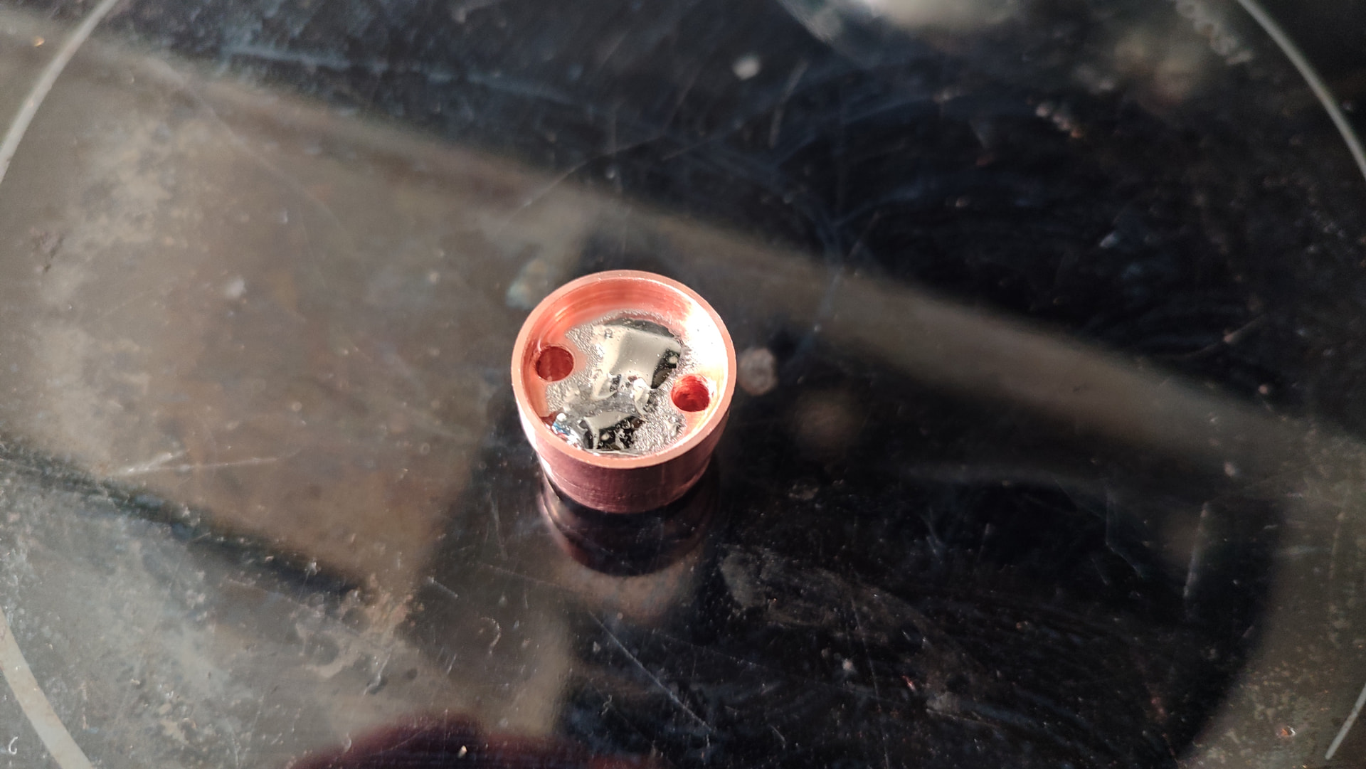
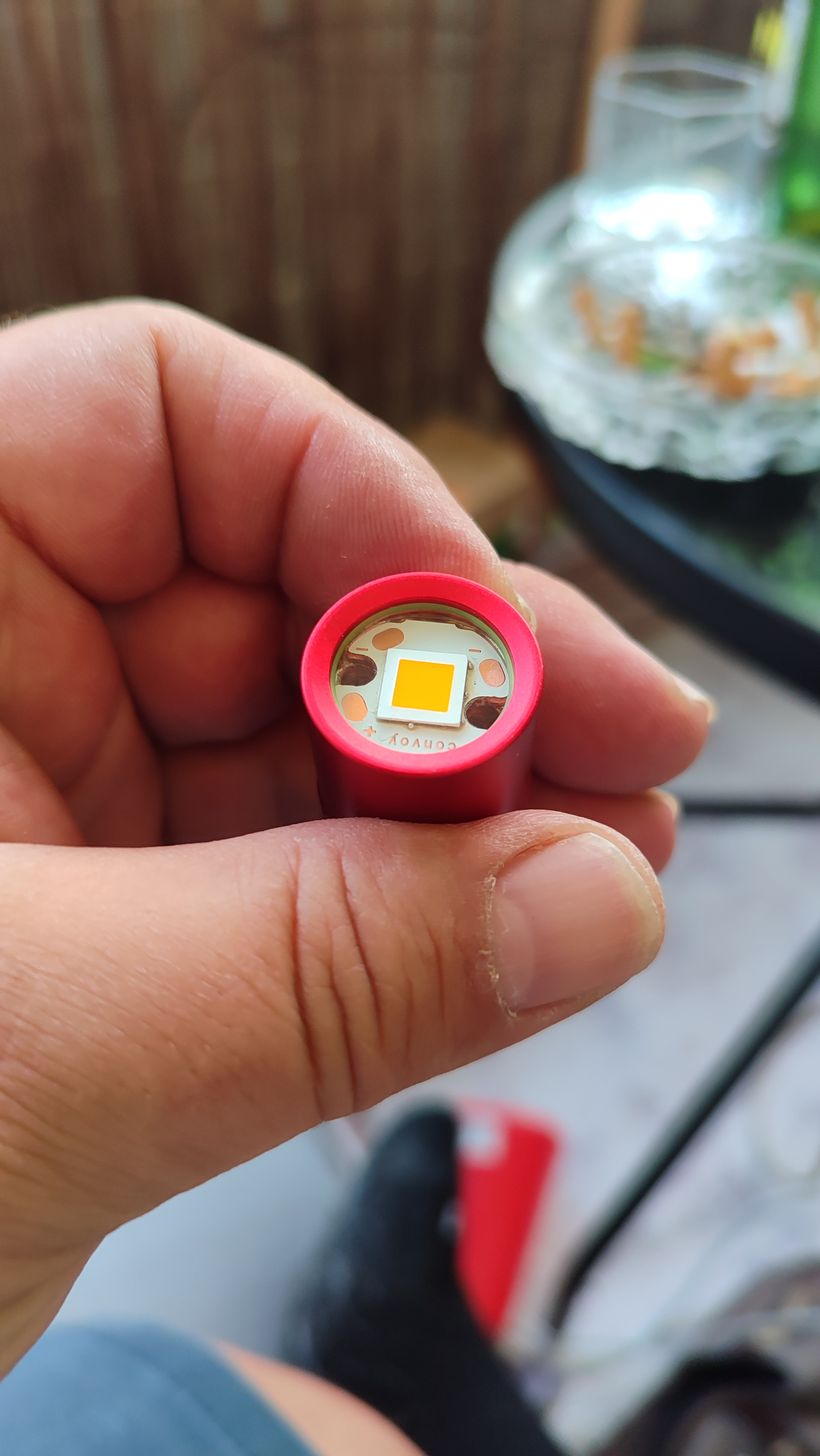
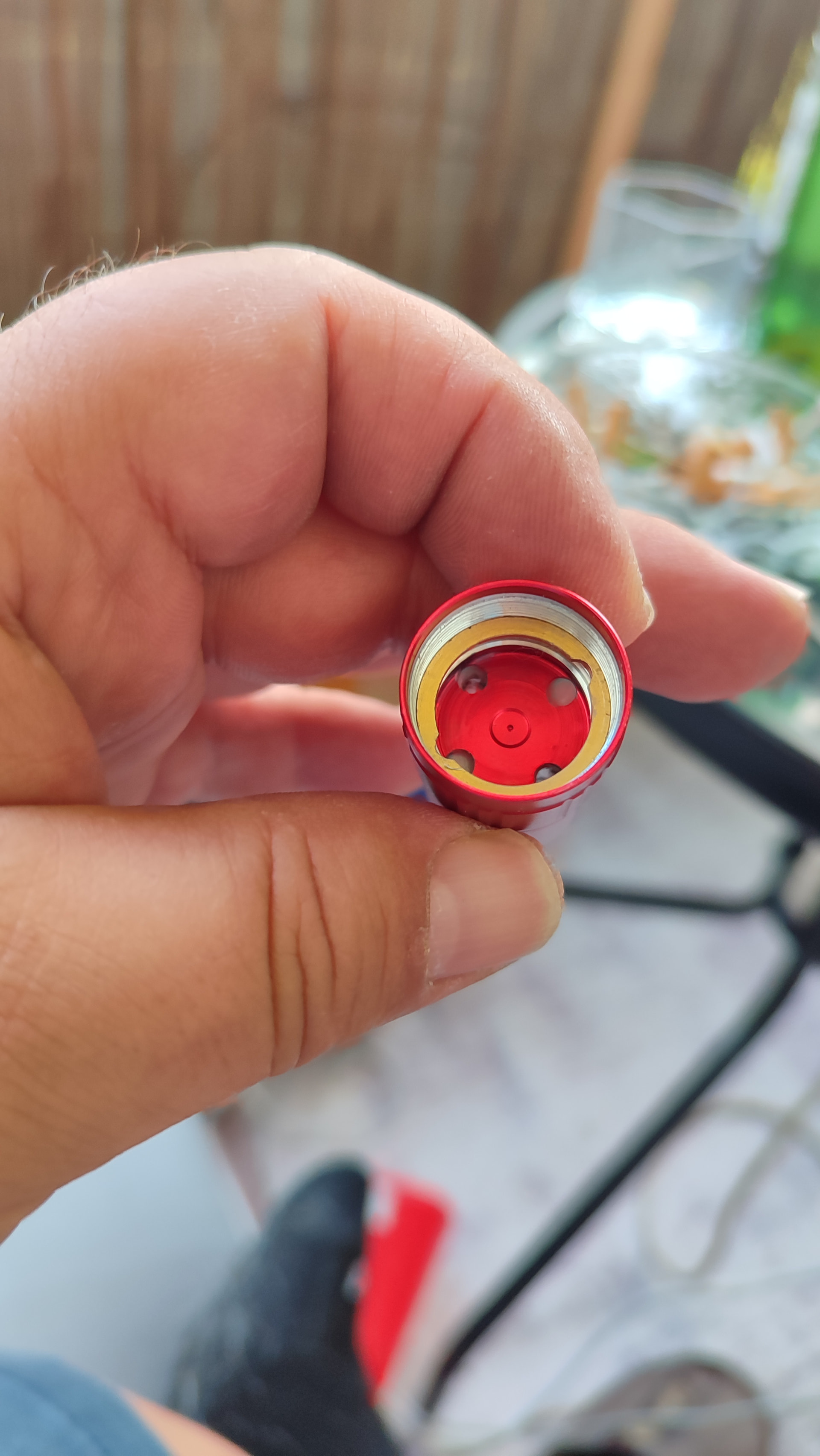
Reflow done, thermal paste applied to the rest of the spacer and pressed inside the body. Had to use grip pliers to alight the wire holes. Probably wouldn’t even need the thermal paste as the fit is that snug but you never know. Need to clean up the squeeze out so the wires stay clean once I pull them through.
Wow those look great! I’d like to do a similar mule some time, I just don’t have a way of easily creating the spacers to hold the mcpcb down.
First mod in a few months: swapped a 3V 5000K FFL5009R out of my Maeerxu XT3 and into my DM11, replacing the 6500K SFN60 that was in it before.
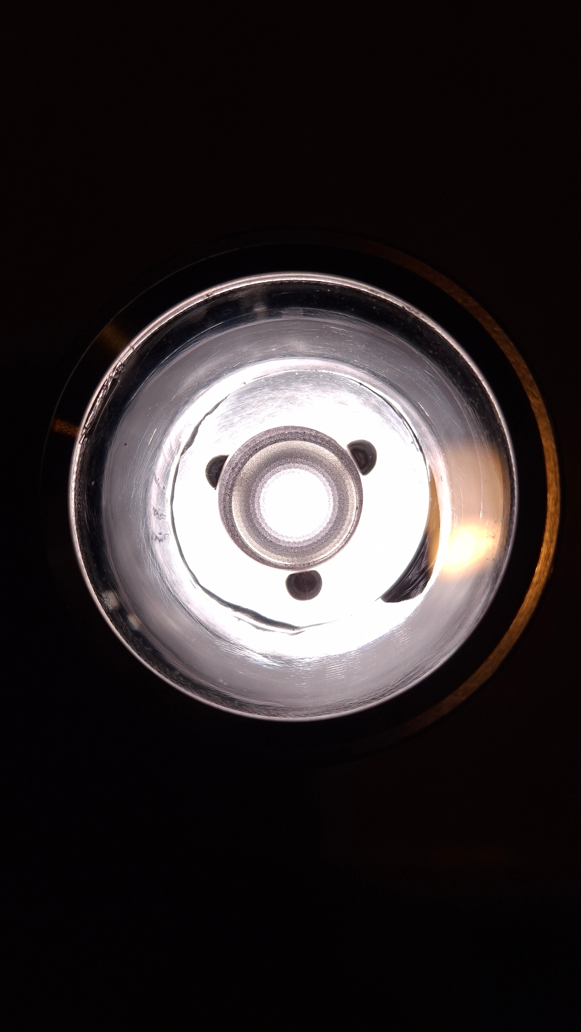
Ran into two things that I have never seen before. First, the reason I wanted the SFN60 6500K out of my DM11 was because it was too green. That same emitter was flawlessly clinically neutral white in a D1K. So the TIR raised the DUV of the SFN. I know that can happen, but the part that I haven’t seen before is that the same TIR seemed to lower the DUV of the FFL5009R. It was so green in the XT3 that I had Lees minus green over it, which was why I did this mod.
The narrow angle TIR creates a horrible donut hole with 5009R, so I used UV glue to patch the broken one. It’s a bit ringy but actually far better than I was expecting. Probably coulda used a bit less glue, but it’ll work until I order a new TIR.