I’ve never worked with this buck controller before, not even built a test circuit.
The MAX16820 has been making the rounds a little bit recently. A couple of members have expressed an interest in building circuits with it, tterev3 has recommended it based on personal experience, and Cereal_killer has shared some WIP boards using it. I’ve looked over the datasheet a fair amount and looked over some other people’s designs, but as I pointed out above I’ve never so much as fired one up. I do have one, so maybe I’ll do that soon.
As per a PM conversation with another member who’s actively working on a MAX16820 based driver, a large electrolytic input cap may be required, air-wired above the rest of the driver.
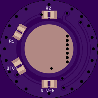
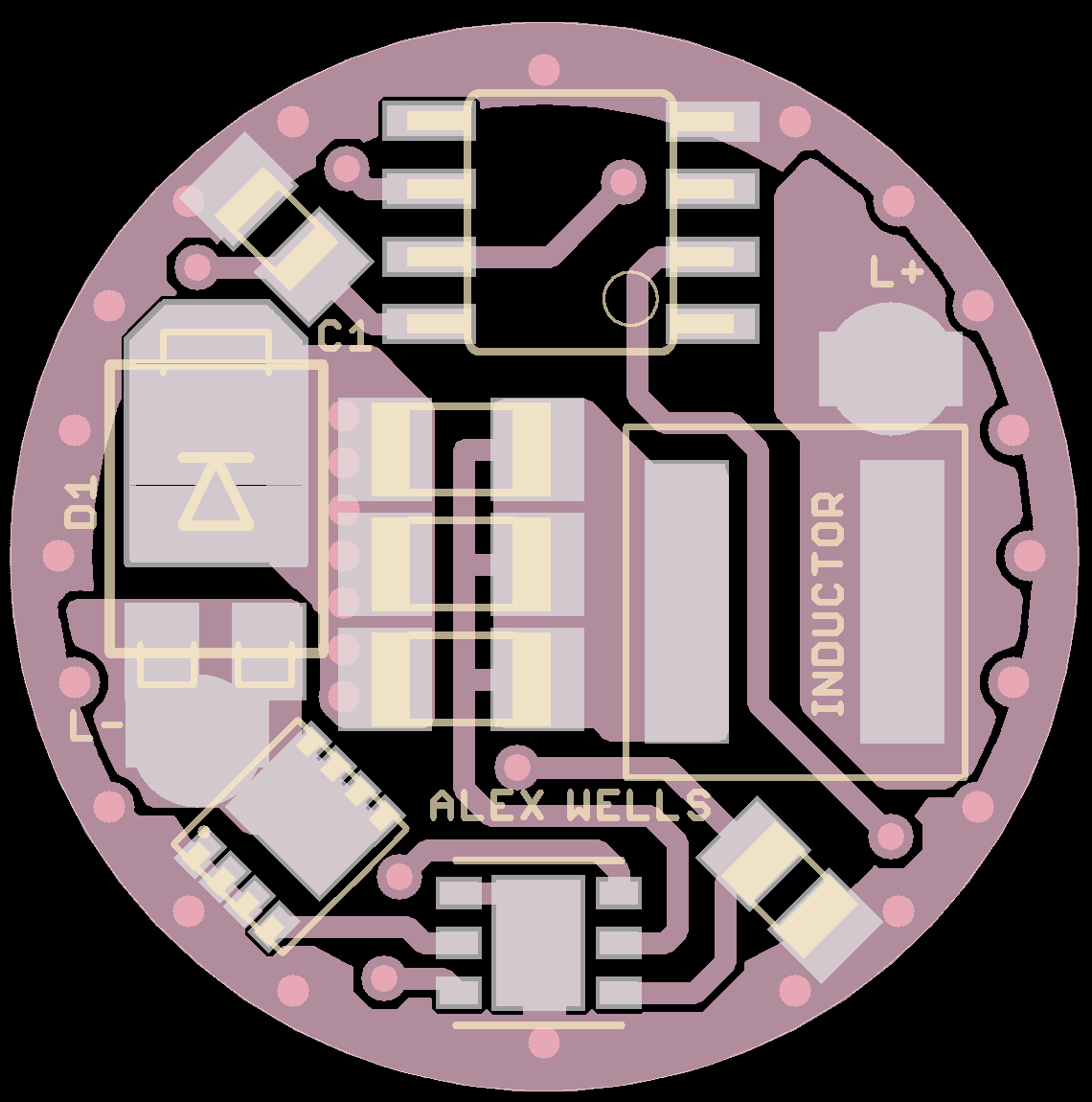
I’m using an LFPAK33 mosfet to save space.
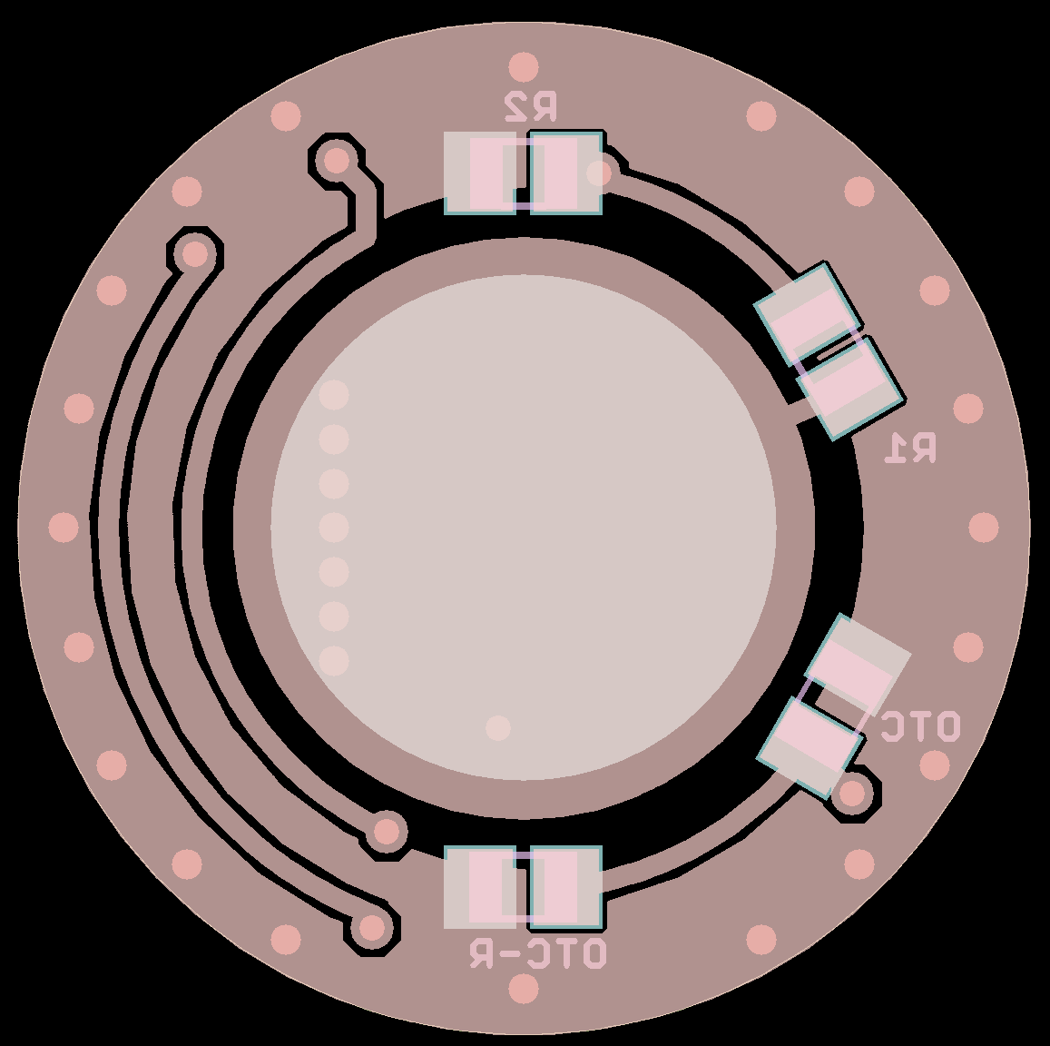
Except for very advanced builders the top will be reflow-only. This is due to the LFPAK33 MOSFET and the flat-no-leads package used for the MAX16820. The bottom can be easily hand soldered if desired.
Ah yes, thanks for posting those links eebowler. I’ve been looking at the datasheet for a little while now, maybe that’s why I didn’t think to post those myself. :~
Now that I think about it, the identifier for the OTC pulldown is not labeled any kind of correctly. I just slapped something on there so people would know what it was, but really it should at least be labeled like Rotc or R-OTC or something, not OTC-R.
I can’t wait to get home to my computer and have a look at your work, one thing I will point out- you mention not being ideal for momentary switch lights, IMO it’s not suitable at all (without a bunch of extra circuitry). The MAX chip has no low voltage shut down and [as you mention] no way to shut off it’s 5V output, if power is supplied it’s always running. Not only is this not ideal, it’s actually dangerous as it can literally suck your cell’s dry (even when the MCU, reading voltage threw the vdivider) is in low power shut-down and not allowing you to turn on the light, even then the max chip is still sucking power out of the cells.
This of course isn’t a proble at all with a clicky switch light.
Not faulting your design or the chip, this isn’t a problem, it’s the design, my finalized version of BU_CK run’s great, as does all of Everett’s project’s (he’s got a few different ones using this chip I believe, at the minimum his EMERALD uses it). It’s a great chip, it’s just not suitable, as used in the above design, for a momentary light at all.
BTW all my testing shows the iC is reverse polarity protected it’s self (and it NEVER put’s out a reverse 5v signal) I believe everett touched on the point in the “component selection” thread too if you wanted to confirm.
Good point Cereal_killer, basically I agree. That said - I think it’s no less ideal than Zener modded momentary drivers, which some members insist on using in momentary lights. (I think it’s actually about half the parasitic drain of the 200 ohm / 4.3v combo?)
I wouldn’t use it in a momentary light.
Thanks for the tip on polarity protection. I suspected that might be the case. I’ll confirm ASAP.
Now that I’ve gotten a good look at it, the only thing that jumps out at me is the small amount of copper around the MAX chip, in my application I’ve found it needed a lot more cooling, A larger copper GND plane under it and / or some thermal via’s. Other than that it look’s pretty good.
I’m exhausted so I’ll come back to this later but it looks like the OTC’s pulldown must be something new to STAR FW that I’m unaware of? I understand the principal, I use that setup on my PIC driver’s, but I am not UTD with all the STAR advances as of late.
Good job alex, I guess at this point I may as well release my file’s for BU_CK (after converting it to AVR, I’m done releasing PIC based drivers anymore)
Thanks. Maybe I should increase the width of the trace connecting the exposed pad to the GND ring. There’s a 0.6mm via right there connecting to the bottom of the PCB as well, but I think the Evaluation Board may be using a much larger via… maybe 1.0mm (?) to do the same thing. I’d better bump up the via and trace just to be sure. I never would have thought that the little controller would need much cooling at all.
The pulldown is there because people (including me) have been running into some excessively low drain rates on the OTC with newer drivers.
I just adjusted the OTC values and have been fine without it, over a wide range of different lights. On the higher drain lights, like the TR-J20, I need to put a lower OT value in there or else you have to click the button so fast that it is hard to change modes. The higher the drain capacity (generally multiple emitter lights) the lower the value I need to go to get similar switching performance. I suspect that this is because the LEDs drain the power for the MCU a bit faster and affect the timing. Did you switch capacitor part numbers?
I do suspect that you will have a problem with a large input capacitor on clicky lights using off-time firmware--one that a pulldown resistor on the OTC is unlikely to help because the MCU will keep running for a while after you cut the power.
I’ve had to go to 240 to get what I considered decent OTC performance (~0.5s reset). That’s close to the edge. I think LinusHofmann hit 250 before giving up and adding a pulldown resistor, this was with an LDO installed. That’s actually not clear though, since some flashing mistakes were made while that testing was done.
I can’t speak for what OTC LinusHofmann is using, but I am using C2012X7R1E105K125AB. My recent problem light was around a 3.5A or 4.0A DD light w/ some A17DD-SO8 version I think. It might have been A20DD-SO8 v24.
You have a good point about the large input cap + offtime setup. We’ll have to see how this plays out, hopefully we can really minimize input capacitance needs.
240? Wow. I've never gone above 130, but usually end up at around 100-110 on the really hot multi-emitter builds. My LDO builds would have that problem because of all the extra capacitance I put on the boards with them, but I'm not going to use them for clicky builds (no real benefit, in my opinion).
On paper a 3.3uH inductor ought to be able to do it for 5A-6A at 2MHz switching frequency, but that's using ideal components (components that don't exist).
In that size I think we won’t get 6A continuous out of anything with a higher inductance than maybe 5.6uH, the real world part just does not exist.
Here’s a rather tall 5.6uH Vishay/Dale part with 7A saturation and 6A “heat rated” current: IHLP2525EZER5R6M01
It’s definitely going to have to be a low value inductor to fit on the PCB. How low we can get away with remains to be seen. Here’s what I have in terms of new-in-package inductors. I do not plan on purchasing more until I see what can be done with these. Inductors are expensive.
Should fit:
Bourns 3.3uH - SRP7030-3R3FM
ABRACON 4.7uH - ASPI-0630LR-4R7M-T15
Should not fit:
Sumida 18uH - CDRH105RNP-180NC
I may also have this and that from scavenged parts, but those do not hold much interest for me since we can’t source them.
I also did the math over again for what I consider a nearly worst case scenario: all the same hardware but driven by 4s1p 4.35v cells for 17.4v Vin! I got 1.4Mhz.
I think the problems show up when you want to reduce current from that point. Dropping to 3A output with the 17.4v setup results in 2.6Mhz: far outside of spec.
I’m using a toroid on most of mine, I’ve used a variety of scavenged toroid’s all the way up to ~12uH*, dont have any idea the current rating’s on any of them tho. For some reason I missed a freaking decimal point when I first ordered parts and I wasted a ton of money on different, large SMD inductor’s that didnt come close to working so I stared looking at other options I had on hand and that’s the route I took.
I’ve got a digikey order coming up (I’m the same way as you man, I keep thinking “if I just wait a little longer I can get next project’s parts in on this one too” lol) soon when I plan to get a selection on known value toroid’s.
I’m working on a 13A version of mine today, I’ll share it tonight with part’s list (also updating the lables and making it a little more presentable and comprehensible to others)
BTW I’m using one of those $20 transistor tester’s to come up with the value of the random parts drawer toroid’s I’m using.
This is a very general question not necessarily related to this project at all…
Theoretically would you be able to accurately control low voltage safety features on a multi series-cell light by monitoring a single cell’s voltage? (never mind the physical challenge of tapping into the series of cell’s to get connections on each side of a single one). In theory, would all the cell’s drain about the same so you could monitor just one of them till it got to your desired low voltage point?
That's also what I got...that at 2 MHz you could get away with around 1.3uH-1.5uH of inductance, but again, that's on paper. I still have a bunch of the Coilcraft 3.3uH that are rated for 4A-5A, so I might shoot for somewhere around 5A to begin with. They are expensive buggers but they seem to be the most efficient space-wise out of all of them.
The higher the differential between your input and output voltage the higher the switching speed needs to be to maintain the same output. When I have the scope hooked up to my evaluation board you can watch the switching speed change as you raise and lower the input voltage relative to the output voltage. The switching speed difference between 8V and 12V input with a single emitter is pretty big.
The MAX seems to be able to switch at over 2MHz, but who knows how stable it is up there, and switching losses will be greater. Best to stay within specifications (as if we were good at doing that... )


 )
)