I recently bought a Wuben E7. I really like the hardware, but wasn’t a fan of the UI. Most annoyingly, and as noted in pretty much all reviews, there’s no way to turn it on to minimum brightness. So that seemed like enough of an excuse to do some modding.
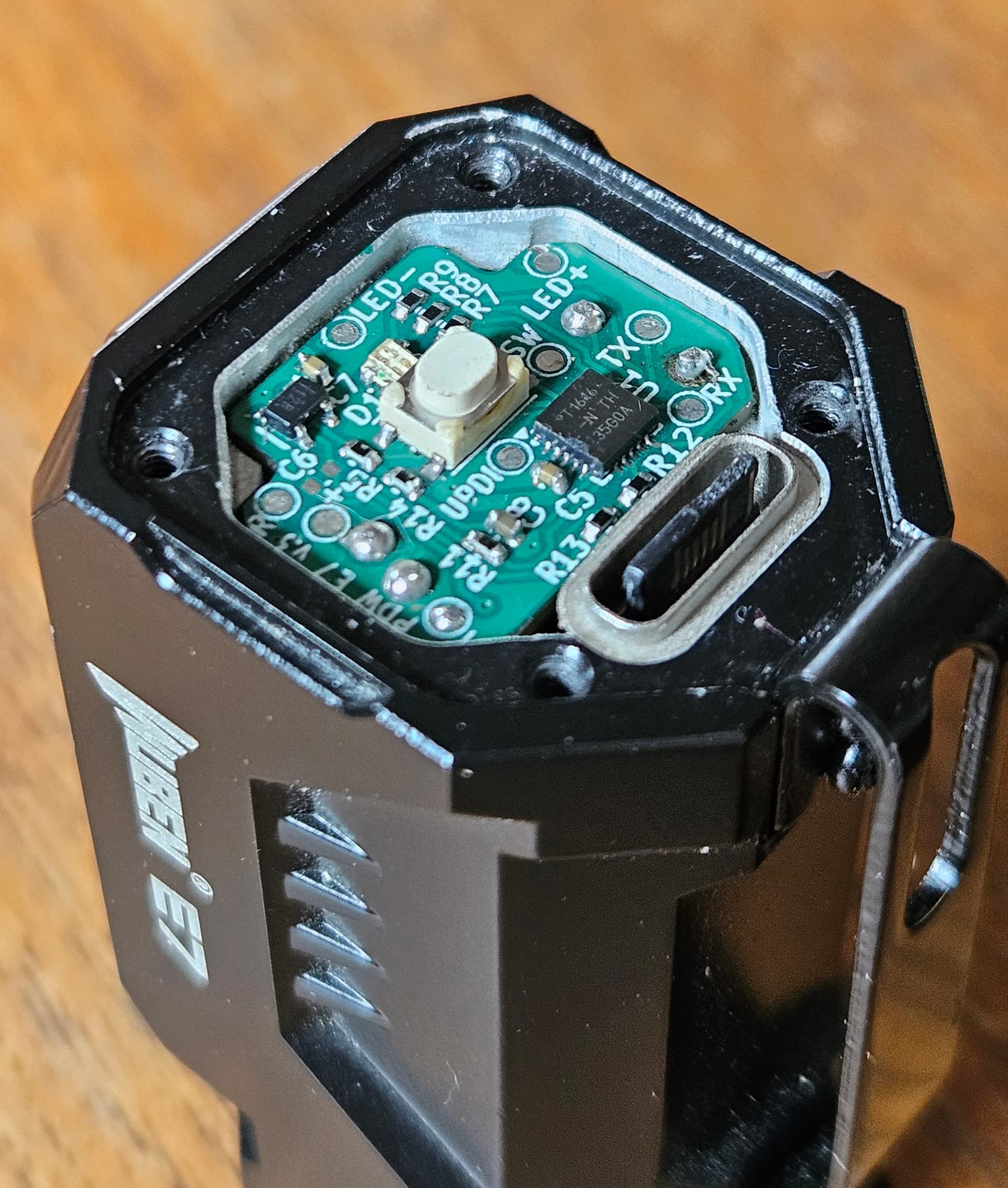
I posted some teardown photos of the stock boards in this thread. There are two PCBs: a driver board and a charge board. I was originally just going to replace the driver but got carried away and did them both.
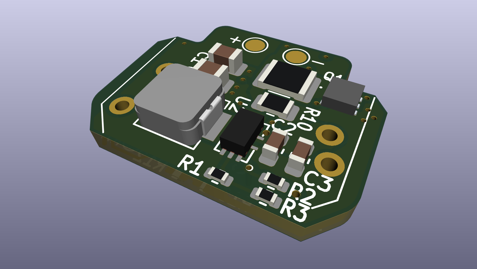
The new board uses an ATtiny1616 microcontroller and a TPS62867 buck driver. The design is based closely on @thefreeman’s HDR drivers.
(try to ignore the slightly melted USB port and the butchered solder pad in the corner)
The driver should be good for 6A, although the control circuit is only setup for about 5.5A at the moment, which is same as stock. More power wasn’t really the aim. At the other end of the scale, I’ve now got a nice 7mA moonlight mode.
Another minor upgrade is an RGB status LED, rather than the original blue/red one.
I’m currently running a simple custom firmware, but I’ve also got Anduril 2 running on it.
I’ll post some details of the charge board later. My main motivation for swapping that was to get rid of the 100µA standby current (roughly 7% battery capacity / month). It’s now < 1µA.
Yes, that’s right. It’s currently got 5Ω for low range, and 10mΩ (resistor) + ~3.5mΩ (FET) for high range.
I have a Python script for generating a table of DAC level, HDR mode, and DAC Vref (for lower levels in each range, the firmware uses 0.55V DAC Vref rather than 2.5V for more granularity).
I’d be interested to know what functions people use for creating a linear perceived brightness ramp. I’m currently using a geometric progression (i.e. the ratio between successive steps in the ramp is constant), which seems to work well enough.
Actually, it’s almost all done with hot air, except the LED and switch which are done last with a soldering iron. I also tend to do the inductor with an iron as they can be quite delicate.
I’ve tried with a hotplate, but I’m not using a stencil and solder paste, so i tend to end up with ICs floating on a ball of solder, and it’s hard to remove the PCB from the hotplate while also pressing down on the IC.
I’m not planning to sell the PCBs, but I’m very happy to share the designs, and I’ve probably got enough parts to make a few one-offs.
Swapping PCBs is a bit awkward as the top PCB is held in place by 4 soldered pins so you need to carefully lever the board up while trying to keep them melted, and the bottom PCB is held in by a retaining ring that’s at the bottom of the battery compartment. I ended up 3D printing a tool to get it in and out.
Oh cool. When you say built in, is that enough for it to cut out/ drop lumens before the torch body gets to 60°C. Or can you solder a thermal sensor to the pcb and onto the E7 body or battery. Thxs
Yes. I’m currently using a custom firmware that I wrote myself, but it can also run Anduril 2. Both can use the internal temperature sensor to reduce output if it’s getting too hot.
My firmware just cuts the maximum power above a set temperature. Anduril 2 does some clever stuff to actively control the output level to keep it at a set temperature.
The microcontroller is well placed to measure the temperature of the driver. Unlike the power PCB, the driver PCB is not connected firmly to the case, so may not accurately reflect the LED or case temperature, but I think it’s good enough.
Im interested how you make a new pcb for the E7. Are you creating the circuits on a new piece of pcb? Maybe some photos may help me see what you are doing.