Here's the graph from the Cree datasheet for reference:
-Garry
Here's the graph from the Cree datasheet for reference:
-Garry
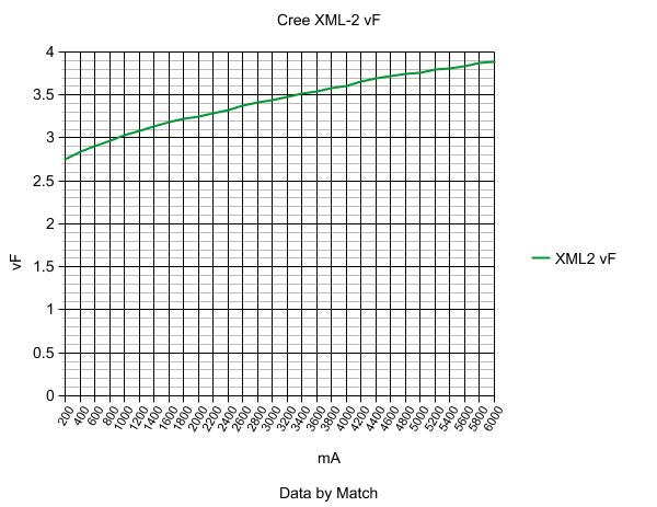
Just in case you would like to check Match's original xm-l2 vf graph here you go. But as Match stated in his OP this one is not accurate.

Thanks jamio. Given that Match's measurements were precise throughout the testing procedure, the Vf plot shows how effectively a direct to copper bond facilitates heat transfer--or rather, how a dielectric layer does not. The emitter mounted on the copper PCB hits "3.5V" at 2.2A whereas the one on the traditional PCB hits "3.5V" at 2.8A. Or, the former emitter simply has a higher Vf, though I doubt this is the case given the increasing Vf disparity at higher drive currents.
If those Vf numbers are accurate, I think it is more beneficial to run an XML2 on an AL star instead of a copper one.
Me thinks you should re-think that statement…
Lets use a random Voltage (Vf) of 3.8V. Pretty reasonable drive voltage for a loaded 18650…
At 3.8V, the XML-2 On Aluminum will be drawing about 4.3A and Making about 1225 Lumens
At 3.8V, the XML-2 On Copper will be drawing about 3.4A and Making about 1250 Lumens
So, On Copper, You can generate Less Heat (12.92 Watts vs. 16.34 Watts), Extend your run-time by 26% and still make 25 extra lumens.
I think I’ll stick with Copper…
PPtk
Thanks for the input. I’ll keep that in mind as I might build a overdriven xml-2 light soon.
In terms of my current idea for a build, I’m not planning on pushing it past 3.0A since this would go in a p60 host. I’ve also been reading about the linear regulators and comparing the voltage sag of the panasonic 3400 cells. To maximize the “regulated” runtime at below 3.0amps, I think the lumen gains over Vf increase is not worth it.
we really need accurate testing numbers
didnt he pull that graph because he just thought the numbers may not be correct and wanted to verify them? could have sworn that was the case…
I have some 5000K/3C/T6 XML2’s and sinkpads on the way… I also have the Sphere ’o Many Mysteries…
Yea that was the reason. I was just assuming they are reasonably close and that I can at least use the data comparatively.
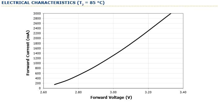
Ask and you shall receive....
I finally got my meter back from cal, and was able to redo the test. The emitter was mounted on a sinkpad.
Time to go update the original post.
Your a champion Match. Thanks. I’m not electrical literate but are the voltage and mA in the opposite places?
Nice!. Watch out the mA and Voltage axis are switched.
I'm sure that is your electrical illiteracy thinking that  .
.
But hey, that is a quite different graph with way different implications for practical use, eternal thanks for redoing them, Match!
Yea Gods!... I can't believe I did that. Thanks for the catch. Fixed!
Your shout Match. Scotch thanks. ![]() You guys are slowly teaching an old bugger new tricks.
You guys are slowly teaching an old bugger new tricks.
Thanks, Match!
texaspyro we’re waiting for you to do something nutso with those emitters. Something with heat pipes and the stirling cycle.
The 20mm ones are going into a couple of these… nothing spectacular: Intl-Outdoor USB Device Charger XM-L T6 Flashlight
16mm into a SRK.
Nice! Thanks for putting in the time for these measurements, they provide some very useful information.
Looks like the old table was in fact quite far off and the Vf is a lot lower than I was thinking. My worries about using the XML-2 + 1 lithium cell + linear driver are not a big deal anymore as I don’t plan on running more than 3amps.
Can someone post a graph with both XM-L and XM-L2 on it for direct comparison?
-Garry