OK thanks for the feedback!!
Thats an interesting twist to things. What did Cree change?
Is a current production, de-domed G2 better or worse then an XP-L HI (factory de-dome) ? Assuming were comparing the brightest / coldest BINs ?
thanks again!!
OK thanks for the feedback!!
Thats an interesting twist to things. What did Cree change?
Is a current production, de-domed G2 better or worse then an XP-L HI (factory de-dome) ? Assuming were comparing the brightest / coldest BINs ?
thanks again!!
These tests show the dedomed XPE2 and XPG2 will give similar throw numbers. And as mentioned above, the XPG2 has significantly more area and lumen output.
The new XPG2 does give lower throw numbers, but lots of them are within ~15% of the old style XPG2, so I would not consider them terrible. For example:
Yeah, I like E2s at 1.05A, maybe 1.40A if I want to push them. I like being able to keep them on 100% indefinitely and not have them cook.
Never used G2s before, so can’t say much if anything about them. They end up seeing at most Vbatt - 0.1V, not counting any IR drops in the switch, springs, etc. No idea how much current you can push through them on a single cell.
I have a dedomed XP-E2 R5 1A running on 6x 7135 = 2.1 Amperes in a Jacob A60.
Must say it works just fine. ![]()
The challenge is focussing the darn thing in the reflector…
It should be ran at 3A if you want it to compete with a XP-G2 in throw.
Naw, all my E2s are on standard Al mcpcbs, not Cu, certainly not DTP. Most of the current would end up just as excess heat, not light. Even at 1.4A, the light curve is flattening out.
Like I said, I like my E2s unstressed, and able to run indefinitely. Kinda need to, in a 1-mode light. ![]()
Yes but OP is not talking about your light, he is talking about some other light, and he said he wants “max lux for throw” not “buy cheap aluminum e2 and run at 50% for mediocre throw” ![]()
But run 100% more current for only 20% more light?
You’d have to similarly cook a G2 to get the same throw.
Dunno, but my philosophy is just because you can, doesn’t mean you should.
The philosophy for throw enthusiasts is that if it gives more lux, you do it.
I can find Djozz’s XP-E2 test, but i think he did test it, but i found a similar test of XP-E2 just now on DTP copper MCPCB and i.m.o. it’s not really worthwhile to exceed 2 Amperes.
Since the XP-G2 has roughly twice the size die, and it does pretty well above 4 Amperes, it will out throw the XP-E2.
But indeed, you’re not gonna get too far with a single cell linear driver, forward voltage is too high at that current.
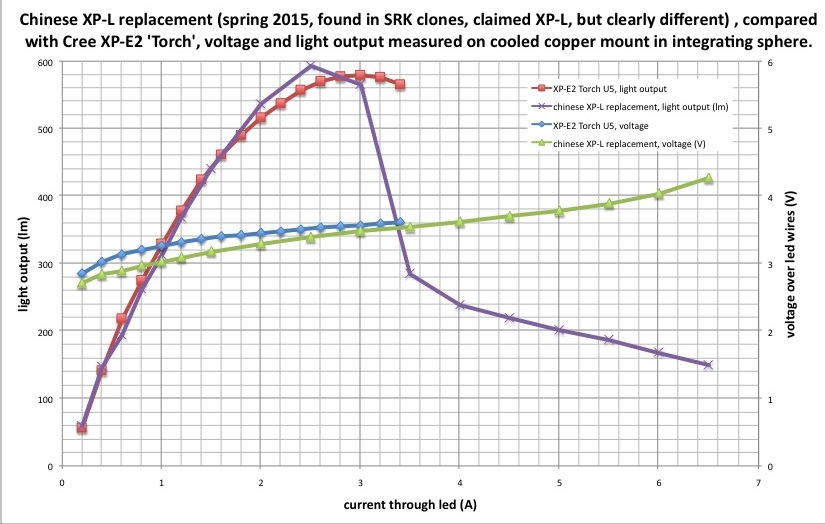
Light output is still rising somewhat at 1A, already almost flat at 1.4A, and peaks at 1.6A. More current, and light drops.
I don’t have any XP-E2s on DTPs, so on a regular Al star, 1A is fairly unstressed, and 1.4A is already peaking.
XP-G2 on Al is peaked at about 2.6A.
Cu DTP changes all that, of course. Smoke ’em if you got ’em.
OK great thanks for the info fellas!!!
At the maximum possible current the XP-E2 has less luminance than the XP-G2 including the newer ones. The Osram Black Flat beats all XP-G2s including the older ones. These things have been carefully measured in the German TLF forum. The XP-G2 only makes sense at really low currents and if the Osram Böack Flat is too much of a hassle (at low currents).
Have they measured the luminance of the dedomed XPG3?
As I understand, part of the hassle (apart from the very inconvenient electrical connection between the thermal pad and led+ ) is that the variation of performance (output, current capability) is quite large and that you therefore have to buy a bunch of black flats and test them and pick the one that has that great performance.
cool… This one here?
Does anyone make an MCPCB for it?
From this thread here…
“A very annoying feature of Oslon Black emitters is that the led-minus is electrically connected to the central thermal pad. This requires, when the led is mounted on a DTP-board, that the ledboard is electrically insulated from the flashlight body.”
This almost seems unsuitable as a flashlight emitter, where the goal is solid thermal contact between the MCPCB and host….
How do you (reliably) electrically insulate AND thermally conduct at the same time?
You can reliably insulate a DTP board from body with an anodized mounting surface
Aluminum oxide is a really good ceramic thermal conductor with 28W/mK of course not as good as aluminium alloys around 200W/mK
It is still 3 times better than Arctic silver thermal paste
How many did you test before you got yours to do 800lm at 4A? Or did you just get lucky?
Yes, there are some things to think about. I would try to use this LED in a light with multiple batteries in series and a buck driver (it has a very high Vf). Some of these lights have reversable battery carriers where both the minus and the plus contacts are on the same side. This means that there should be no current flowing through the body of the light. In that case there is no need to insulate the LED. Otherwise one could use a non-conductive thermal adhesive (or a paste and plastic screws). High quality thermal pads are another option. Also there a some drivers where the minus of the batteries is connected directly to the cathode of the LED. In that case it also wouldn’t matter.
You can use standard PCBs for XP-LEDs, just use less solder and press down the LED. The solder pads of the Osram are a bit smaller.
@djozz: unfortunately, yes. The problem seems to be that not all of the samples have the same thermal resistance (at least this is my guess). Not all of the still get brighter at currents over 3 or 4A.
In the end it all seems to be worth it… Die 1 Million Lux Bimmelglocke:):) | Taschenlampen Forum