YuvalS’s Modification Class, 13th Annual BLF/OL contest entry topic

I noticed that not many people joined the challenge this year, so I decided to participate and hopefully encourage others to join as well.

As mentioned before, I’m unable to build anything physical this year. Instead, I’ll be developing software for the “anything goes” modification category.
If the community or organizers decide that software isn’t eligible, I might switch to the Hand Made (Basic Tools) category and join with the simple prototyping light. Otherwise, I’ll just use the competition timeframe as motivation to complete my project.

The Idea

My vision is to create a tool that allows people with no programming experience to generate firmware for flashlights and flash it to the device without any additional hardware.

The main goal is to make the process as simple as possible so that anyone who knows how to use a Windows PC can create their own custom firmware according to their personal preferences.

The Challenges

To achieve this, I need to solve three main problems:

  1. Firmware code generation
  2. The flashing (burning) process
  3. Installation and compatibility across different systems

The Approach

I’ve been thinking about this idea for some time and have done a bit of research. I believe it’s achievable by combining several open-source projects.

Flashing process:
This can be handled using CircuitPython, a beginner-friendly version of Python developed by Adafruit for microcontrollers. It allows you to write and run Python code directly on the device. Flashing the firmware is as simple as a drag and drop operation. Just like copying a file to a USB drive, you simply drop the code onto the driver MCU that is connected to your computer by a USB cable (same USB port use for charging).

Code generation:
My plan is to write a set of basic, parameterized functions for all necessary actions such as detecting switch clicks, long presses, and battery levels. The user will then be able to:

  • Set the number of modes and light levels for each mode
  • Define how to switch between modes
  • Configure responses to events such as timers, temperature, or battery level

All these settings will be managed through a simple graphical user interface (GUI), so no programming knowledge will be required. Based on my research, this GUI can be built using standard Python libraries.

Compatibility and packaging:
To make the tool as accessible as possible, I plan to package the GUI and code generator into a single executable file, so users won’t need to install Python or any libraries. It looks like this can also be done entirely with Python.

The Learning Curve

Although Python seems to cover everything I need for this project, I have very limited experience with it, so I’ll be learning the language as I go.

What do you think?
I’d love to hear your thoughts, suggestions, or any advice from those with experience in Python or similar projects.


11 Thanks

Wow, this sounds really cool! :smiling_face_with_sunglasses:

1 Thank

Code should be written to support dedicated hardware. What hardware will be supported?

I am still investigating it and not yet decided. There are many boards that support CircuitPython but I want to take into consideration more parameters such as power consumption in off mode, charging circuit, number of PWM channels and cost.

I also have no idea on how much memory the generated code is going to take. Obviously it is much less memory efficient than a dedicated code

1 Thank

It would be a huge loss for the community if they decide your project is not eligible.

I would consider myself generally “technologically challenged”, in the sense that it takes me forever to make sense of new concepts I encounter in user manuals/instructions if they are not defined explicitly or hidden behind an impenetrable wall of jargon. I also seem to have exceptionally poor luck when it comes to compatibility issues whenever I install anything or try to interface between different devices. For these reasons, I tend to shy away from anything that involves interfacing with a computer.

At the same time, I think most mechanical clicky UIs on the market are inexcusably poor; even Convoy’s 12 group UI suffers from poor mode spacings, strange mode group choices, lack of granularity, excessively bright moonlight, etc, just to name a few issues. Same goes with pretty much any E-switch UI that is not Anduril.

If you can find a way to make customizable mechanical switch UIs a reality, it would be a game changer.

1 Thank

Today I spent some time researching microcontroller boards for my upcoming project. My main criteria were:

  1. CircuitPython support – I wanted a board with official CircuitPython support, so I could rely on existing documentation and guides and avoid spending too much time on the initial ramp-up.
  2. Built-in LDO and battery charging – Ideally, the board would work with a Li-ion/LiPo cell and allow charging via the same USB port used for programming. This isn’t strictly necessary for development, but I want to demonstrate a proof-of-concept “complete solution” with USB charging.
  3. Cost – I want to keep the price reasonable. If the board is too expensive, it could prevent others from experimenting with my project, especially if I hope the community or brands adopt it.
  4. Flash memory – I don’t yet know the size of the auto-generated code of my project, but I want to avoid memory limitations.

Luckily, the CircuitPython website lets you filter boards by “battery charging” which made the search easier. My final candidates are:

Board Flash Sleep Current Charging Price
SuperMini NRF52840 (ICBbuy) 1MB Unknown 100/300 mA Low cost
Seeed Studio XIAO nRF52840 1MB + 2MB <5 μA 50/100 mA $9.90
Seeed Studio XIAO ESP32C6 4MB 15 μA 100 mA $5.20
Seeed Studio XIAO ESP32C3 4MB 44 μA 100/350 mA $4.90
Seeed Studio XIAO ESP32S3 8MB 14 μA 100 mA $7.50

If price were not an issue, the XIAO nRF52840 seems to be the ideal choice. However, since I’m concerned about cost, I will probably go for the SuperMini NRF52840 from AliExpress, which also offers a higher charging current, and hope to reduce the off current to below 10 μA. If I’m unable to find a 2–3 $ source on AliExpress, I will go for the next cheapest option, the ESP32C3, due to its low price and decent charging current.

1 Thank

After some thinking, I have decided to go with the SuperMini NRF52840 for my project.

My main reason is cost. I hope this project will be adopted by others, and I think keeping the price low will make it easier for more people to try it out. In my opinion, this is what the budget lights forum is all about. It is not about high-end, expensive lights but about simple solutions and community effort that enable surprisingly powerful features without breaking the bank.

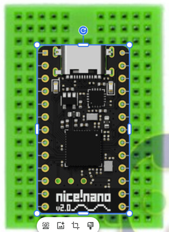
To kick things off, I placed an order on AliExpress for the SuperMini NRF52840, together with a SYB-170 tiny solderless breadboard and some electronic components for my prototype. The breadboard is very small and limits the number of components I can add, but according to the ‘very sophisticated illustration’ I have generated, I think there is enough free space for all the essentials. This setup should allow me to pack the board, components, and a LiPo cell into a compact package to create a functional light that supports drag-and-drop USB programming.

Now I just have to wait for the shipping.

4 Thanks

It has been a while since my last update, so I wanted to share where things stand.

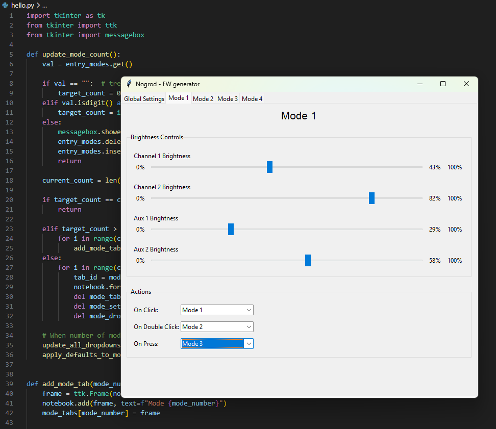
A few days ago I downloaded and installed Python and VS Code, and I started playing around with GUI development to understand the options and capabilities. After some digging in forums and watching YouTube tutorials, I decided to go with Tkinter since it’s powerful, built into the Python installation, and well-documented.

I experimented with different Tkinter widgets that I’ll need for my GUI: text boxes, dropdowns, tabs, sliders (not sure if I really need sliders, but they look cool!). I managed to build a basic interface that controls most of the options I want, but it looked a bit old-fashioned.

While the design isn’t my top priority, I think some users might avoid something that looks outdated. So I looked for a better styling option and found ttkbootstrap, which gives Tkinter a much more modern appearance. It definitely improved the overall look of the GUI.

At this point, I believe I can build a GUI that lets users configure all the relevant settings for generating a firmware. The remaining gap is handling the settings defined by the driver manufacturer such as the number of input/output channels, their names, voltage readings, etc. I still need to figure out an easy way to load these parameters into the tool.

Another open issue is implementing saving and loading user configurations. I don’t want users to manually re-enter all settings every time they run the tool just to change one brightness level. So I want to add the ability to save favorite configurations, reload them later, or even share them with a friend.

While I’m waiting for the board and components to arrive, I’ll keep experimenting with the GUI and exploring the best way to store settings and what file format I should use.

4 Thanks

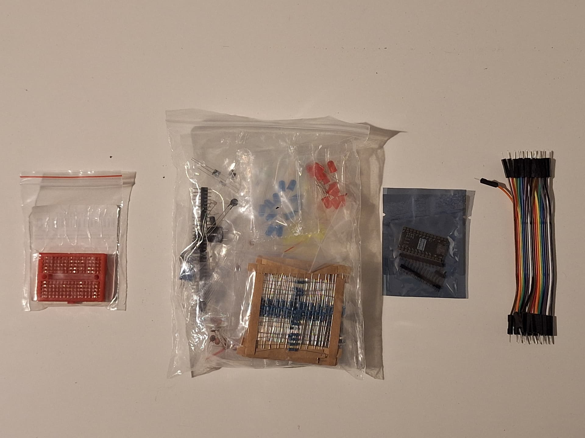
I just got the components by mail.
Got the SuperMini board, mini breadboard, wires and electronics “starter kit” I orderd for the switches, resistors and LEDs.

The firs step is to understand how to set the bootloader and load some Hallo World blinking script using the drag and drop USB type C.

Fingers crossed Aliexpress sent me a working board :crossed_fingers:

1 Thank

After getting the package, I started digging into the CircuitPython tutorial.
The first steps were surprisingly easy:

1. Connecting the board
I plugged the SuperMini into my computer using USB-C, and it immediately appeared as an external drive.

2. Installing CircuitPython
This step was super simple:

  • Download the correct CircuitPython file from the official website
  • Drag it onto the device (which appears as CIRCUITPY)
  • The board automatically resets and mounts again with CircuitPython running

After that, any Python script I copy to the CIRCUITPY drive runs automatically.

3. First test – blinking LED
To confirm everything worked, I wrote a small script to blink the onboard LED.

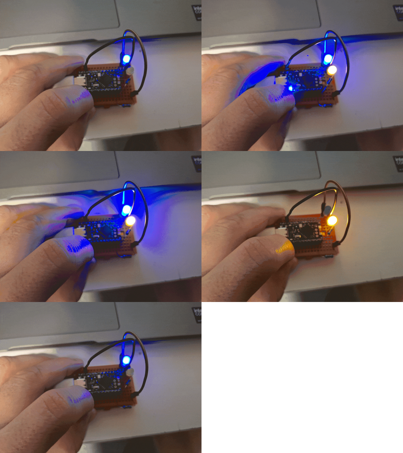
4. Building the prototype “flashlight”
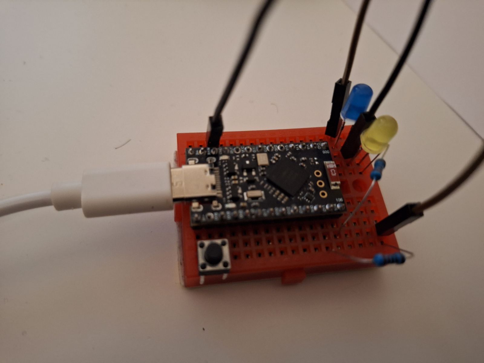
Once I confirmed the board was working, I soldered header pins and placed it on a breadboard.
I started with a single external LED, and once that worked, I added a switch and a second LED.

5. Current “flashlight” setup
With two LED channels and a momentary switch, I was able to test more complex firmware.
I now have a 4-mode setup that uses a single button to detect short and long presses and control both LED channels.

20251130_034954-ANIMATION

Testing all of this proves that my vision is totally possible.
I managed to get each piece working separately, and now I just have to combine everything and add more features and functionality.

7 Thanks

Very cool! I’m excited to see this progress. I dabbled in some microcontrollers for fun earlier this year. I think I have that one you’re using but I started with an ESP32. I have a feeling your project here will inspire me to try it out again sometime soon. Keep it up!

1 Thank