Zebralight SC64 Anduril Edition

Actually all colors bleed like this, although blue less, probably because of the position, but also it’s weaker than the other colors (the blue red mix is more toward pink than purple), I should have used a slightly lower resistor value.

a lower resistor, maybe, but this still makes it look unique for a ZL.

Oh and thanks to Gchart for adding DAC control for the Atinny 1 series in Anduril 2, I wouldn’t have been able to do it and it makes the drivers much simpler (less components) and the ramping very smooth (perfect transition between the two power ranges).
Also thanks to Toykeeper for Anduril!
As well as id30209 who taught me how to open Zebralights without breaking the glass :smiley: . Also Bob just a few days ago about how to remove the switch retaining ring.

you have the greatest support behind you there.

So cool! Could you tell us more about the driver’s specs like regulation performance, efficiency, etc?

It’s a 6A constant current HDR buck driver, like this one I made for the FWAA , but limited to 4.25A as I thought that was more appropriate for the LED and host.

The efficiency is the same as this one :

I call it a HDR driver because it switches between two different current sense resistors to achieve a large current range. The ramp looks like this :

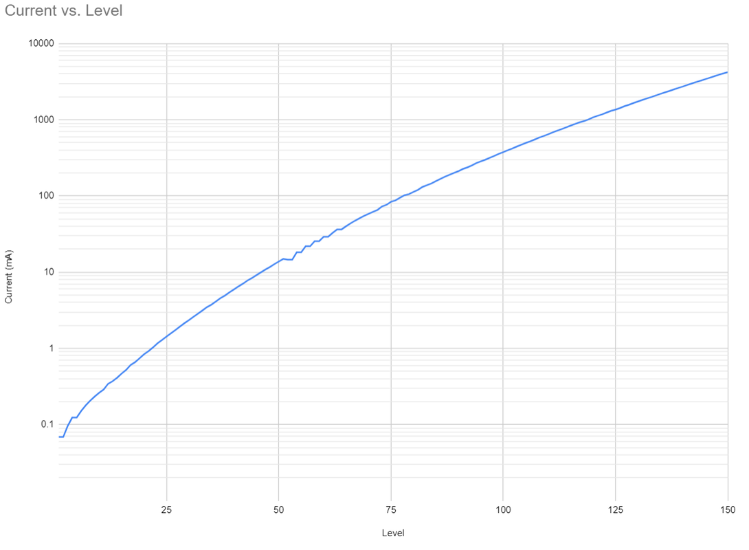
(Shows a minimum of 70uA but I manually modified the calculated ramp afterwards to go down to 28 uA, can do 14 uA min).

The thermal regulation isn’t working very well (steps down too soon) at the moment though, I’m pretty sure that’s due to the MCU (thermal sensor) being on the same PCB as the LED so it heats faster than the body.

Awesome, congrats!

WoW

Great work and skills :+1:

Regards Xandre

What happens when LED voltage is higher than battery voltage? (e.g. when you go to top of ramp when battery is low)

Is it possible to compensate by setting thermal threshold higher within Anduril?

Dud driver built last year :

Versions : 3 PWM controled ones and the DAC one with fewer components :

The current starts to drop at some point, however it should be at a lower voltage than the SC64 LE because my driver has a lower dropout voltage and the 519A has a lower Vf than the LH351D.

Doing some quick measurement, with Vin (+pogo pins and -tube contacts) =
3.37V : 4.24A
3.33V : 3.90A
3.26V : 3.36A
3.18V : 2.71A
3.10V : 2.14A
2.97V : 1.30A
2.95V : 1.22A

Then it steps downs due to LVP, a bit too soon actually, it seems to read a lower voltage than in reality.

It helps a bit but it’s not a good solution since the light will get too hot afterwards.

Maybe something like in the Lume1 FF code will help, it only steps down from turbo when the temperature reaches therm_ceil + TURBO_TEMP_EXTRA. But I don’t think this function has been added into the main branch.

nice but - guessing it is out of my budget!

Lights like this and others that only enable the FET at the very last ramp step (i. e. lights with the lume driver like FF NOV-Mu and FW3X) are the reason why we need the ability to switch the thermal regulation behavior at compile time. I'd love to update my lights with dc/dc + fet drivers to newest anduril but turbo mode would become pretty unusable as it is now :/

.
C’est si bon

Wow, freeman…wow! Excellent work!

Super nice. This looks like the bleeding edge of flashlight tech.

That’s one thing I really disliked about the Lume1 driver. I found with my Lume1 FW3A I could only stay at turbo for 2 seconds. Then there would be a giant step down in output as the thermal regulation stepped down causing the FET to turn off.

With that sort of behavior why bother even including a FET on the driver board? It just feels like false advertising when you find the 2800 lumen light you thought you bought can only do that for 2 seconds then steps down to 1000 lumens.

Since I prefer pocket rockets, I found I much preferred the stock FW3A driver as it actually had a usable turbo. If I have to choose between having turbo versus having greater efficiency at lower outputs, I would take the turbo.

The other thing I didn’t like about the Lume1 was its lack of reverse polarity protection which led to me accidentally frying the driver. Oops!

@Firelight2

Wait, the Lume1 doesn’t have reverse polarity protection? Oh boy I didn’t even notice.

The original Lume1 driver has no reverse polarity protection. Stick an 18650 in the wrong way for even half a second and the driver’s toast.

However, I believe there is an updated version, the Lume X1 (or something like that), which does have reverse polarity protection.

Aside from the thermal regulation tweak mentionned, dynamic PWM should now allow to PWM the FET silently and get intermediate levels between 100% FET and regulated DC/DC.

The problem is at what PWM level do we switch from FET to DC/DC ? FET being unregulated whe don’t know what PWM level corresponds to e.g. the 3A of the BB converter of the Lume1 FW3A. I don’t known if there is a good solution for that.