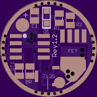
17mm Rev1.2


…………………………………………………………
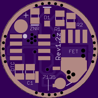
17mm Rev1.2z
Same as above, but BR is removed to make room for being Zener-ready. Note: D1 is opposite polarity compared to the other boards.

…………………………………………………………
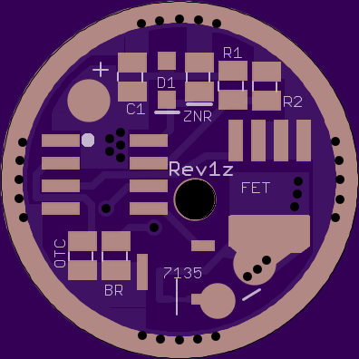
20mm Rev1z
Same features as 17mm Rev1.1z, plus:
- 2.2mm through-hole for LED+ bypass
- 7.5mm spring pad
- Generous 2.9mm edge clearance
Link to 19mm.
………………………………………………………………
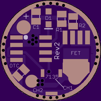
17mm Rev2
This version has a different focus. Rev1 was focused on providing the most possible control over a primary LED or controlling a secondary LED with lower current. Rev2 is more for lights that have 2 primary led’s, like the C22c or some bike lights.
As it sits, it is a FET+6 layout, basically a DoubleDown driver with 2 extra 7135’s. The FET and the 6 bottom 7135’s are on the two PWM outputs of the Attiny13a. If you cut the trace under the 7135 on the top, it separates the 6 bottom 7135’s from the FET. So you can have 2.28amps regulated for one output, and the FET for the other output. It will also work with existing firmwares, you only need to adjust mode levels to your liking. If you use an Attiny25/45/85 instead of a 13, you should be able to output PWM from Pin3, activating the 7th 7135 on the top, turning the FET side into a FET+1 side (and still leaving you with 6*7135 on the other side).
Of course this is all pretty experimental. I don’t know how the FET side will behave amperage-wise when both sides are on full.

……………………………………………………………………
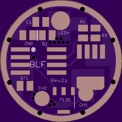
20mm Rev2z
Same features as 17mm Rev2, but is also Zener ready, Attiny85 ready, and has eight 7135’s on the back instead of six.
…………………………………………………………………
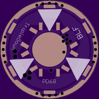
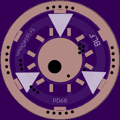
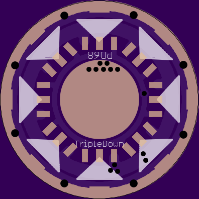
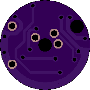
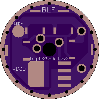
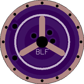
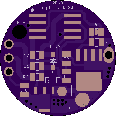
TripleStack Rev2
This is the TripleStack. It has 3-channel functionality for a single output. I don’t think there is any way to use it with different outputs like you can with the other TripleDown versions. This version consists of a “bottom” contact board that holds the FET and most of the 7135’s, and a “top” board that holds the rest of the parts. You will need five 0.025” header pins to connect the two sides. The advantages to this board is that it will give you a cleaner look once installed, you can use a normal sized spring instead of being limited to a tiny spring pad, and parts were added that used knowledge from the Q8 driver to increase stability. The disadvantages are that it is harder to build (tight on space), you will need to make sure you have room in your pill for the stack, and it only has five 7135’s instead of the 7+ that other versions have.
Order Links:
15mm Top board
17mm Contact board
18.5mm Contact Board
20mm Contact Board

……………………………………………………………………………
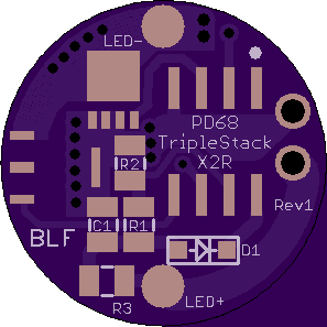
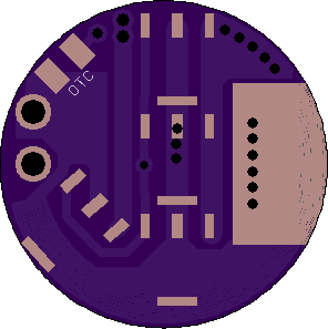
TripleStacks made specifically for the EagleEye X2R and X6R.
For the X2R, you just remove the top board on the original driver, get rid of the extra header pin, and solder this in its place. For best performance, you will also want to solder the big pad on the bottom to the top of the USB connector on the charger board. Headroom is tight, but the LED wire pads should line up perfectly with the holes in the shelf. If you order from Oshpark, be sure to get the thinner 0.8mm size. Also note the FET is the smaller LFPAK33 size.
……………………………………………………………………………….
For the X6R you will also use the stock pins. You will run ground wire from the charger board to the pad/via by the FET. The LED+ hole is over a spot you can carefully drill through the charger PCB to bypass the spring/PCB. I’ll illustrate all of this with pictures once I finish my X6R mod. Also be sure to order this one in the 0.8mm size.

 It would be worth putting together a couple samples to send for R&D
 - Didn't think my stare was worth much. I can follow it - just noticed your comment, so spent a couple more mins on it - looks good to me..