The 4th Annual BLF / O-L Contest; MtnDon's Entry, Hand Made Class

This is a “hand made” entry.

This project evolved through several incarnations over many months of day dreaming. There were a few constants. Use of a remote phosphor was one. A second constant was that this would be a camping lantern design, not a traditional flashlight. I wanted to light an area, not objects in the distance. I think the remote phosphor design is a natural for a lantern type of light. I guess that remains to be seen. :laughing: I want extended run time more than brilliance and bedazzlement. Lastly, I want to use some wood parts.

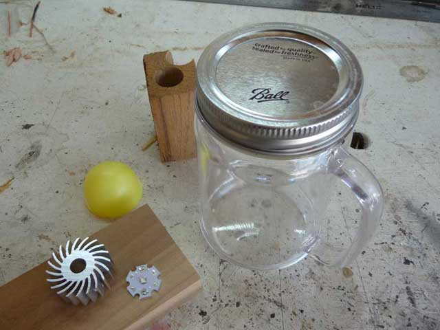
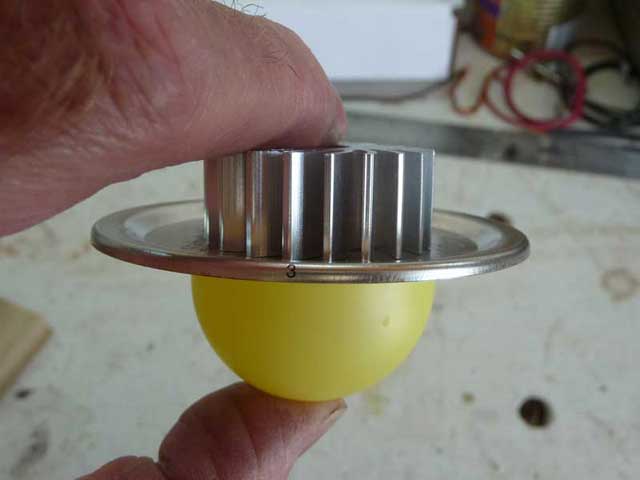
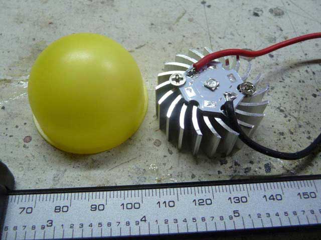
The remote phosphor comes from DigiKey. (photo) DigiKey stocks a small number of the variety made by Intematix,under the name ChromaLit. FYI, data sheet is here. The one I selected has a color temperature of 5000 K. I do like neutral more than warm light. It is a dome shape, 26 mm high with a base diameter of 42 mm.

Intematix makes a variety of forms, shapes and sizes in an assortment of color temperatures. One difficulty is finding a source for the shape/type that is desired.

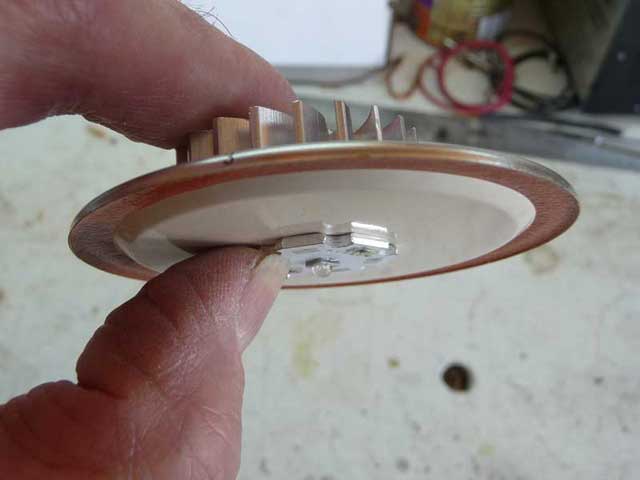
Remote phosphors utilize special emitters. I have some Cree XT-E Royal Blue emitters. These have no phosphor built in. Output wave length is 450 to 455 nm. I bought from an ebay seller. The emitter came on a 20 MM aluminium MCPCB. That should be sufficient for the envisioned low amperage use.

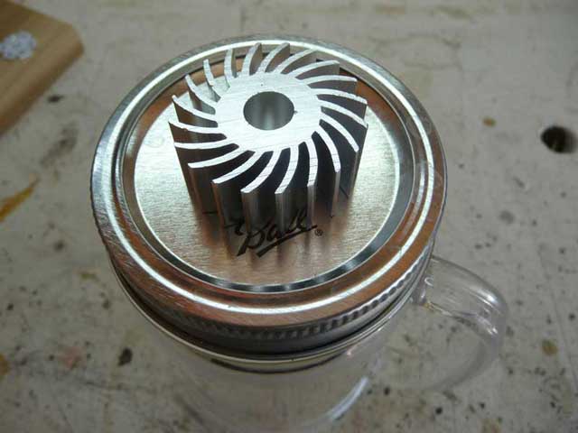
I have a 35 mm diameter heatsink I got from fasttech.

The driver: I have a Nanjg 101-AK-A1 on order. It has custom firmware, no memory. The levels, in percentages, are… 2, 6, 15, 28, 50, 100.

I plan to use at least 4 parallel connected 18650 cells to extend the illumination duration. I chose the 30Q’s because I have some of them doing nothing but taking up space. Flat tops.

I am going to try to incorporate a small digital voltmeter readout. That could be useful. Perhaps a later version with power pack ability as well as a built in charger will be attempted if this prototype works out.

Photos, we have photos. :smiley:

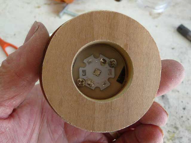
The phosphor dome is 42 mm across the bottom. The heat sink is 35 mm diameter x 16mm high. The XT-E is on a 20 mm star.

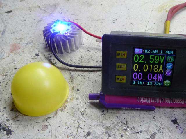
Illumination test, 2.59 volts 0.018 amp. The “royal blue” color of the bare emitter is evident.

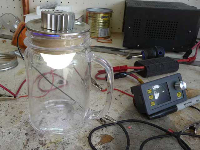
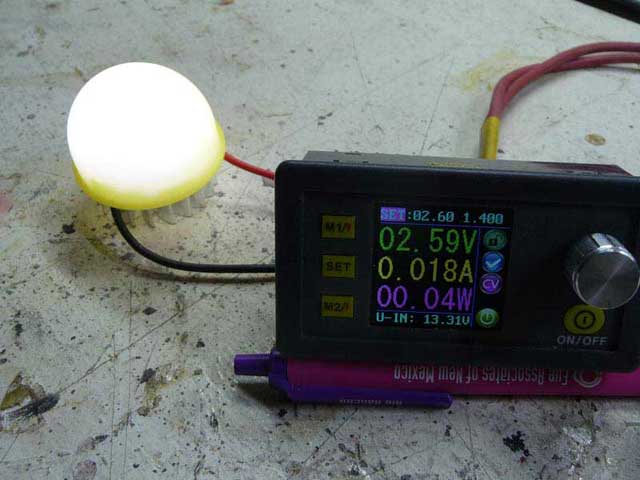
Next is the same power settings with the phosphor dome placed over the emitter.

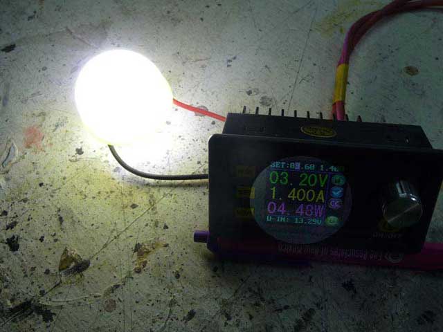
The emitter with phosphor dome with the voltage cranked up and the amps at 1.400

Hmmm… the workbench top sure appears beaten up in the photos. :smiley:

Thanks for looking.

reserved

Interesting concept in using the remote-phosphor set up. :+1:

I love your concept!! Best wishes MtnDon!

Great concept, very interesting build :+1:

More uniqueness, what a great idea.

Good luck with the build, MtnDon.

Nice to see the remote phosphor setup being used.

Magic led. This will be interesting. :+1:

Thanks for the kind words.

Now there will be a lull in activity. I need to get the present stage of my home remodel project completed before I can spend much time on this. New ceramic tile floors and 33 new red oak stair treads have some higher level priority over this ’light. I don’t know how that happened. :wink:

Never seen anything like this. Question - could you use any led that has had the phosphor stripped off? For example, I know I am not the only one who has stripped an mt-g2 trying to dedome it. Could an mt-g2 give more efficiency at these lower power levels?

One would think that any LED without the phosphor layer should work. I am no expert… am just beginning to dabble in this remote phosphor / royal blue wavelength thing. The claim is that an emitter such as the XT-E royal blue, is more efficient with a remote phosphor than the same emitter with the phosphor attached. Cree and Intematix have assorted literature if you search online.

FWIW, I have also seen quad emitter versions much like an XPH35/XPH50 in choices of 6 and 12 volts. And just now I did an ebay search and found a 3 volt quad version here.

It’s a neat idea for ambient lighting but counter to the point source we need for a focused beam. This contest is a great place to explore such notions as it probably gets wider notice and there isn’t a presumption of throw.

Well, I stole a couple of hours from home improvements this afternoon. :open_mouth:

Has anyone wondered how this led and remote phosphor was to be utilized in my lantern light? Here’s what I have been thinking of.

That is a mug that has a Ball Jar type threaded top. Sixteen ounce size. have a pint, eh! I found it online at “discountmugs” They sell promo items with company logos. They also sell samples with no logos. It comes without a lid so now my wife’s pantry is short one lid and ring.

The plan is to mount the heatsink on the top of the lid…

Heatsink, lid and LED sandwich…

Plan A would be to mount the phosphor dome right over the LED / MCPCB…

That places the dome up and behind the metal screw on lid band. I’m not sure if that would cut light output or not. Plan B is to make a spacer to move the dome down. So the making of a prototype spacer is featured next. (that will post shortly in the next message)

After I have the spacer done, when it is dark tonight, I can compare Plan A to Plan B. Unfortunately it will have to be a visual estimation comparison as I have no lux meter

Hi MtnDon,

Nice concept.

Photo’s not showing as of Sunday Night GMT +1 (England).

Cheers,

Splott-Light :slight_smile:

I’ll have a mug of your finest hi cri please to go with my BLF.

Prototype spacer. I also have other reasons for using a spacer. I’ll get into that later after I see if there is any light output penalty…

First step is to use the drill press to hole saw a blank…

The first blank was done with a 2-1/4” saw and was too small. This one with the 2-1/2” was a tad too large to fit inside the neck…

The drill press was used again along with a rasp and then sandpaper…

That did work although the blank turned out slightly out of round. End grain and side grain of the wood removed at different rates I guess. Then I sawed out the center…

We have a donut!!

I used 80 grit paper on the benchtop to hand sand down the high spots…

To locate the position of the heat sink mount holes I made a pencil tracing. Yes, I am a mystery / detective fan!! :wink:

The punch marked the holes…

With the holes drilled through the lid, the LED was trial fitted with the heatsink on the top side of the lid. The spacer was temporarily fixed in place with double stick tape…

Like so…

Some temporary power hookup and we have light!!!

Now to wait for nightfall to see if the spacer causes any appreciable reduction in light output. Don’t know if many photons will get absorbed by the wood. Maybe line the spacer with aluminium foil?? (I never should have put the window in the workshop / garage….)

I had a moment of brain fade and forgot how to post images here. :person_facepalming:

Cool, you can pick up some efficiency by sticking a reflector in the donut. Anything that fits will recover energy lost into the wood. I think your right about end/side grain. To stay round the wood can’t wobble and the cutting surface(rasp, sandpaper, whatever) has to be fixed. At least that’s been my experience. Threads also seem to grab unevenly in the chuck so I use a carriage bolt with the end removed. Sometimes I’ll press a bushing into the table but that can be a false security and may or may not put more pressure on the chuck.

If I have time tonight I’ll try it in the darkened shop with
(a.) the spacer as is now
(b.) the spacer with an OP reflector from an S2… it fits the hole and thickness of the board used
(c.) no spacer, dome right over the led.

I dug out my old Sekonic L28C2 photo light meter… really old school thing. (That dates me I think… :laughing: ) A selenium cell and analog meter. I have no idea if it will be able to discern differences at the light levels I intend.