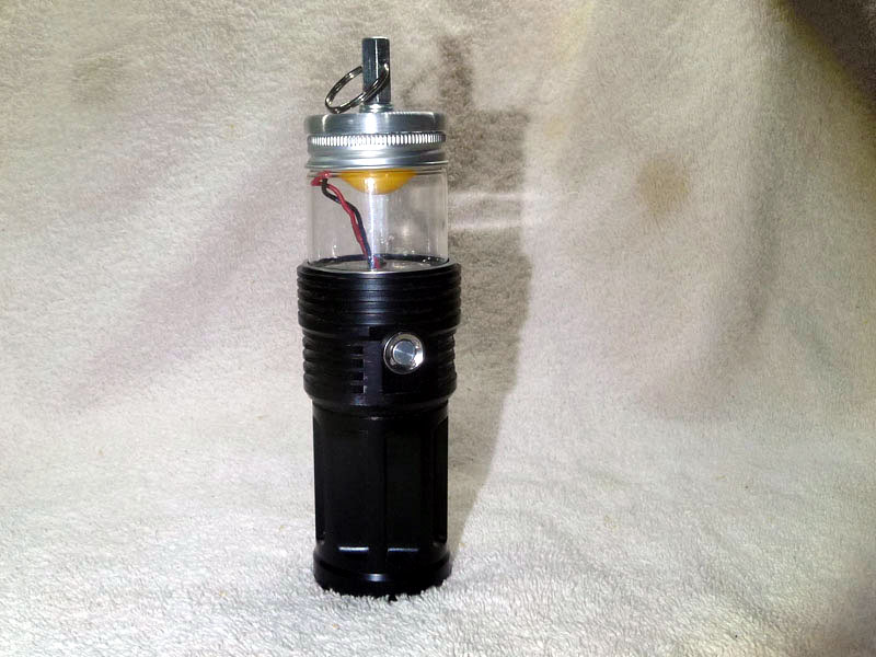
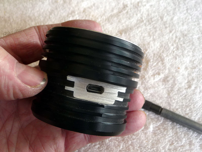
I filed out a recess for the micro usb port for the charger. A little rough. I painted the surface with flat black auto paint. The port is weather resistant from the application of silicone sealant around it inside the head.
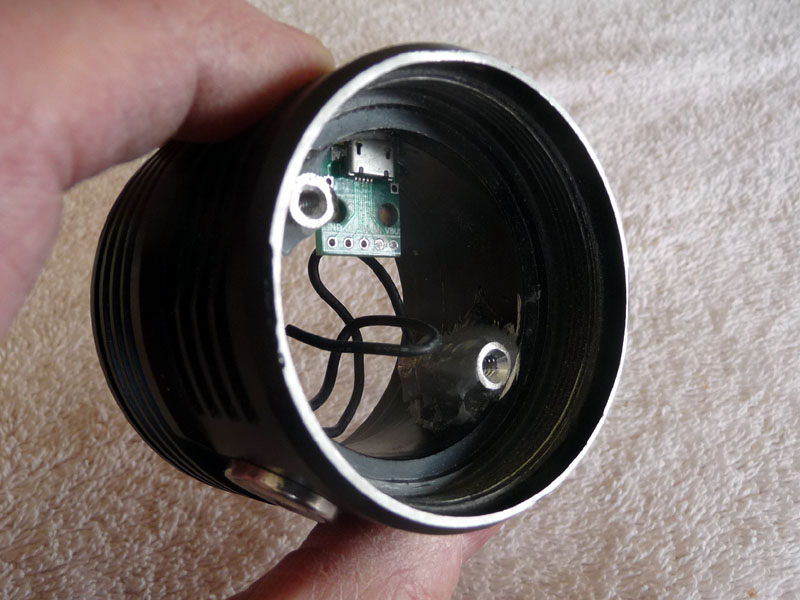
The usb board prior to sealant being applied
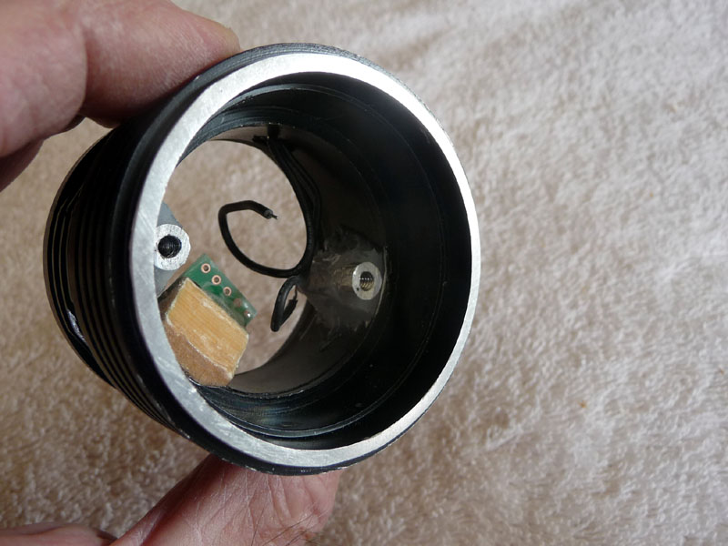
The usb board mounts to a small wood block (where would my lights be without some wood!!) glued to the inside of the head.
I used a 46 mm SRK driver board to support the new driver. The original from this light got lost someplace around here during the wait to finish. Mtnelectronics has these old ones on a $2 clearance. I used some kapton tape to cover all the mount points on the other side of the board.
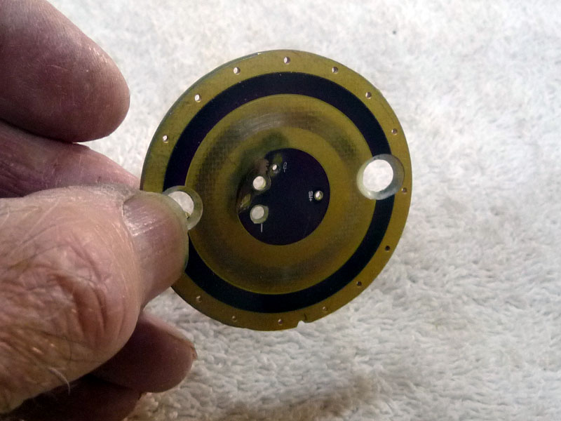
Yes those are some strange holes bored in the board. Explanation to come.
Those holes are to secure the board in the head. Rather than just rely on a friction fit I wanted machine screws. In part that was because of an error on my part as well as I knew this would go together and be taken apart a few times. I used nylon screws and they are well recessed to avoid cell top interference.
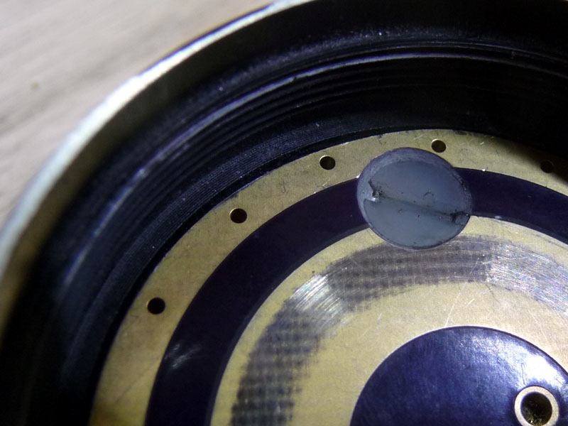
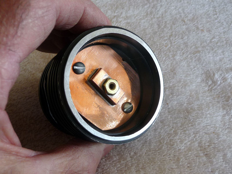
I used a 17mm driver from Lexel. It has Narsil, 2 x 7135 and no FET. I added the kapton tape to the main board after these pictures were taken. Inside the head you can just see one of the two threaded sleeves I epoxied in place for mounting the driver board and the copper front plate to.
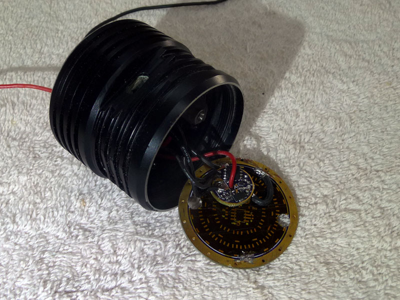
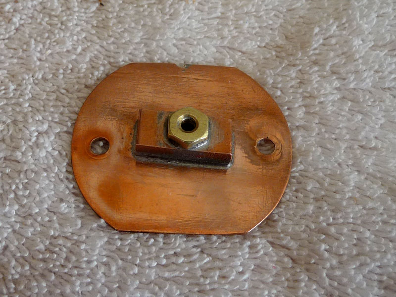
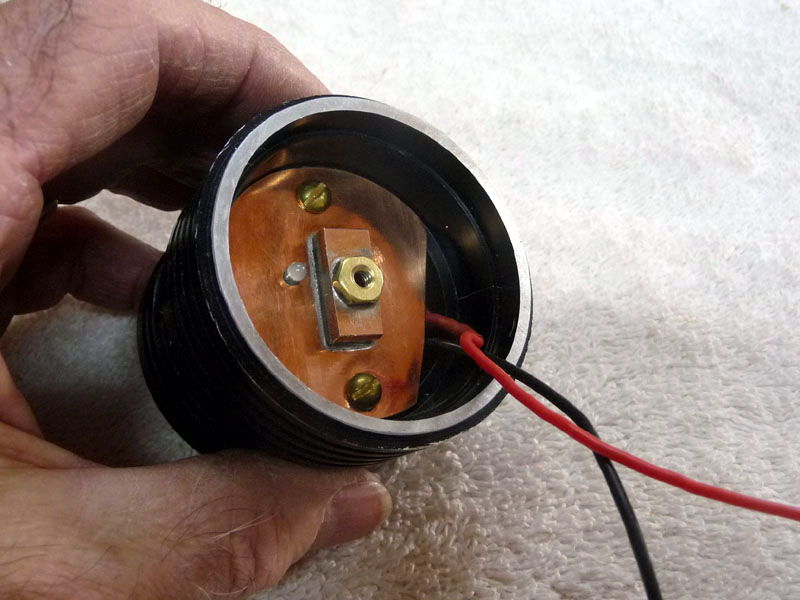
A shot of the front plate with a threaded mount visible inside.
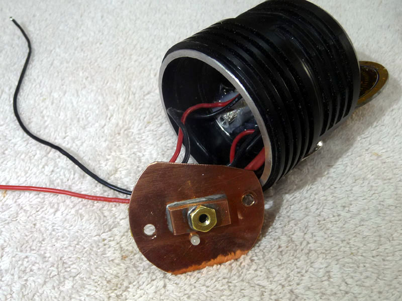
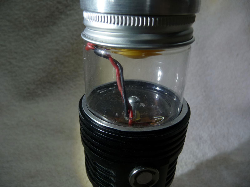
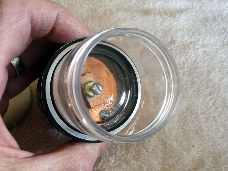
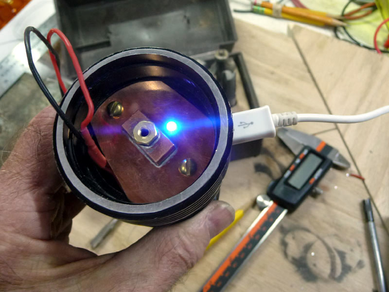
The other side of the copper plate with the TP5000 charger board. I mounted the charge indicator led through the copperplate. It is visible inside the lamp house on top. I was going to insert it through the side wall of the body but changed my mind as the wiring was becoming crowded.
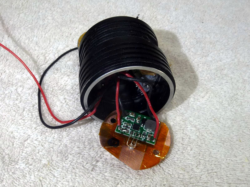
Another shot of the driver end…
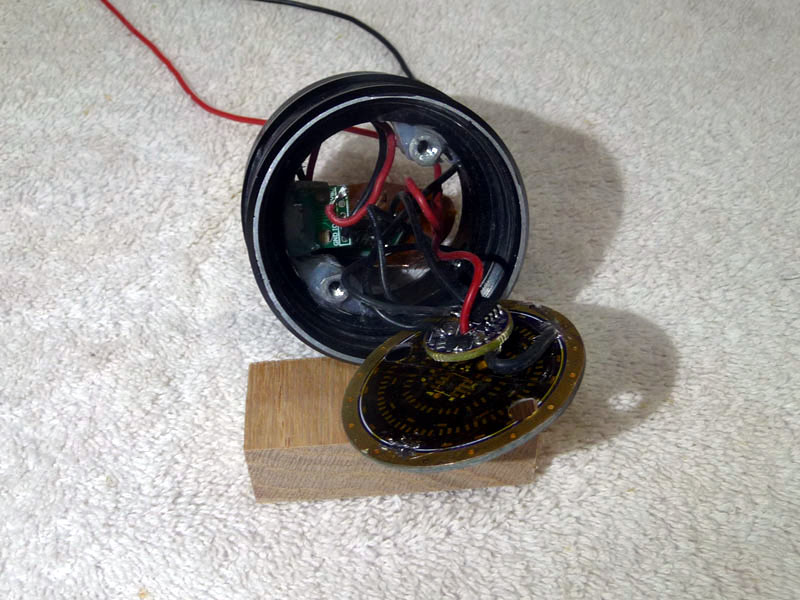
The odd shaped cut out in the copper plate is to provide ample space for threading the wires to the led.
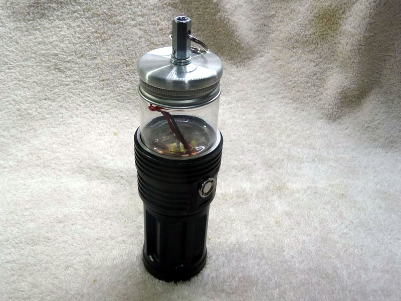
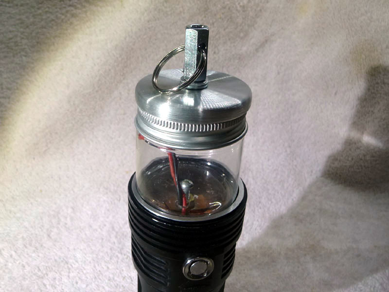
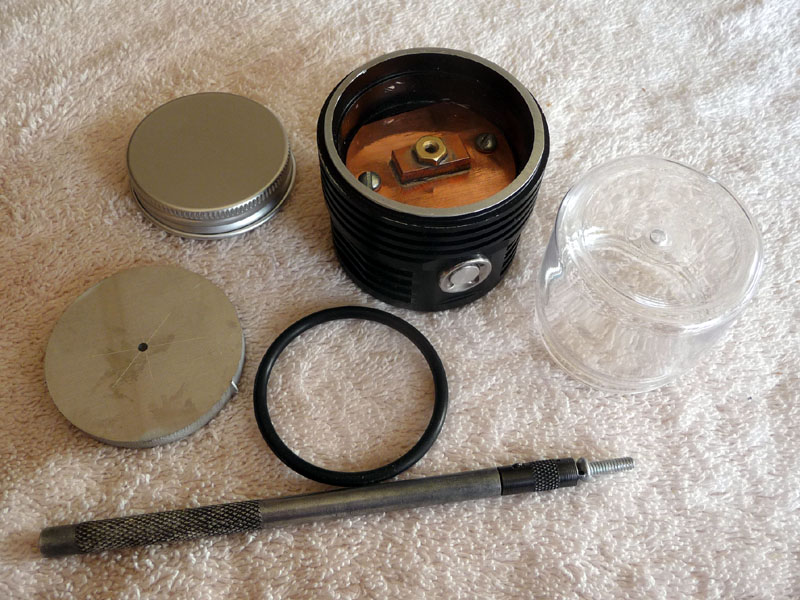
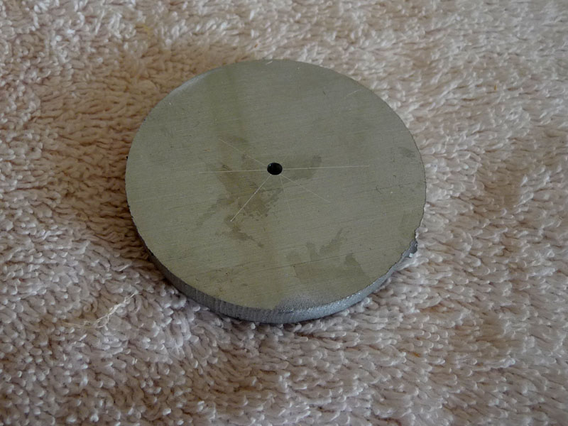
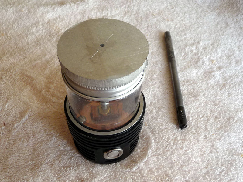
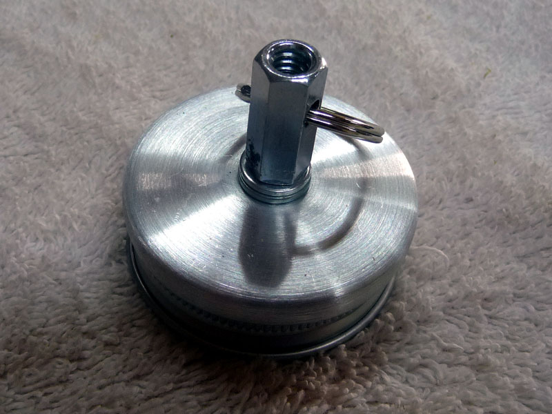
A closeup of the head hanger. I mounted the aluminum disc in the drill press chuck after tapping the center hole 1/4x20. Then spun it and used a file to smooth, finishing with a couple of sandpaper grades. I used a coupling nut, drilled a hole sideways and added a split ring.
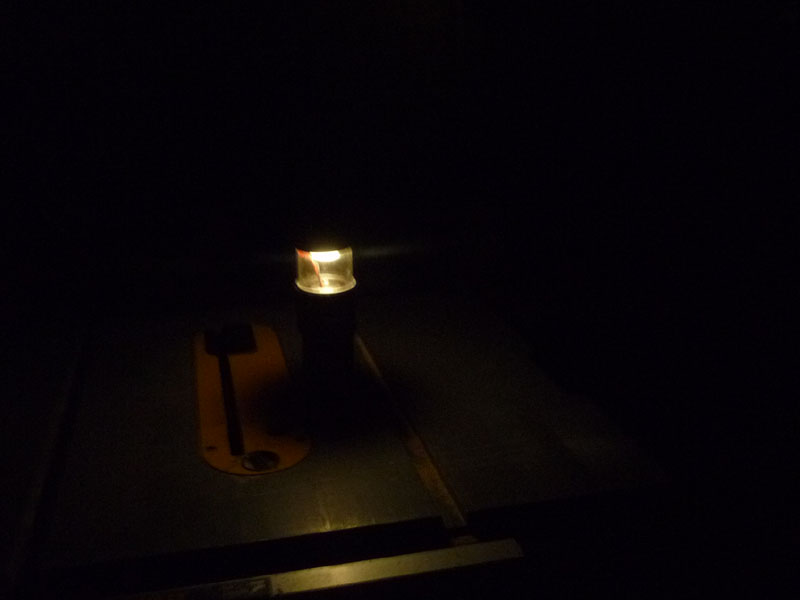
I made a maddening error. After checking and double checking the 2 color, 3 lead, indicator led connections for the charger I still managed to mess up. The convention with these boards is to use the red color/led to indicate a charge in process and then the blue to indicate charge completion. I got the leads reversed. :person_facepalming: I don’t know if I will tear down and switch the leads or not. For now I am contenting myself with the rationale that the Blue light indicates “Being charged” and the Red light indicating the light is “Ready to use”. :person_facepalming: Of course that is the opposite of the other lights I have with chargers built in. We’ll see how that goes. 
Here it is in full charge mode…
Anyhow it was fun and I thought I’d show this.
