Hello BLF,
TL;DR:
I built a tailswitch system comprised of two PCBs, called the GFS16 System. First is a 18mm Taillight board which provides the regular taillight, and also features a battery sensing system to change the LEDs colours when the battery voltage is low (Rev B features 5uA standby current!). Second is a 16mm Tailspring/FET board, which allows replacement of the switch for a super low resistance FET, allow for the best performance in high current flashlights. All PCBs are up on OSHPark as well as parts list so you can make your own! The components are small so please keep in mind that these may be challenging to solder.
As some of you might know, I've been making some small boost drivers for my flashlights in a little quest to make a nice, small, very bright flashlight. While making these (specifically with Convoy S2+ hosts since they're affordable and good quality), I came across a thread about lighted tail-lights (https://budgetlightforum.com/t/-/32103). That seemed like a fun thing to do, but I figured maybe I could make some small improvements!
My Convoy S2+ hosts came in a variety of tailcap versions, some with a black rubber boot, and some with a black metal switch. While waiting for my driver PCBs to be fabricated, I figured that I'll just make something for fun! 
Most regular DIY tailcap lights are very simple - they're essentially a set of one or two PCBs, which replace the PCB/washer combination on stock tailcaps. These new PCBs hold the main clicky switch, as well as the battery spring, a few resistor (and/or trimmers), and a variety of LEDs. When the light is off, the driver leaks a little current through, and this is sufficient to light up the LEDs in the tailcap. In order to make the tailcap light visible, modders often swap out the rubber boot for a clear/white one, or use clear rubber gaskets.
One of the things often requested was to build in some kind of battery indication. This seemed like a good feature to have.
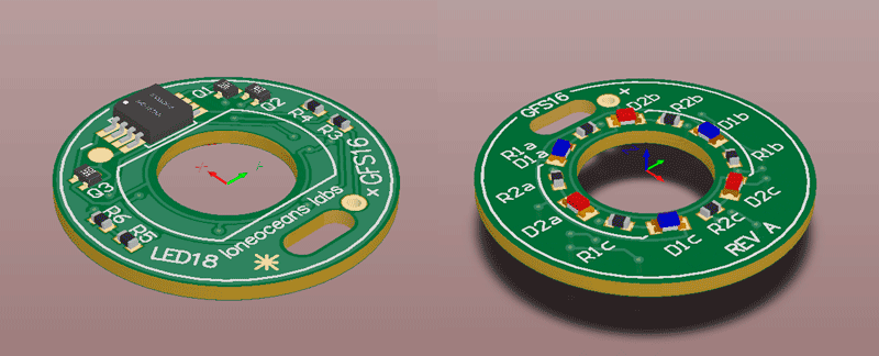
So here's what I came up with!
You can populate the LED ring with a variety of different LED colours, and choose the brightness based on the series resistors. Also note (importantly!) that I made sure there are no components on the periphery of the top side of the LED board, since this part supports the entire weight of the retaining screw from the other side. I saw some other designs with resistors placed on the keepout area, but I guess it's better to have a flat surface.
But what's all the extra stuff on the board?
And how does it indicate battery level?
Is that a Microcontroller on board and do I have to program yet another controller? (no of course not :) )
Here's what the board does.
There are two voltage set-points which you can set using R3/R4 and R5/R6. The first is a low-battery threshold voltage (for example, 3.3V), and the other is a critical battery threshold (for example, 3V). In the example above, I've configured the tail-light board to:
- Light up Blue by default (obviously you can change your own colours if you want)
- When battery level drops below 3.3V, Light up Red
- This is a good indicator that maybe you should charge your battery
- When battery level drops below ~3V, Turn off all LEDs
- This is a good indicator that your battery is really low, the board turns off LEDs in a bid to prevent draining the battery flat too quickly
However, this isn't done with any microcontroller on board!
Instead, the board features a small dual comparator with a built in reference voltage. The first resistor pair sets the first trip voltage, an the second resistor pair sets the 2nd trip voltage. I've chosen a specific push-pull comparator so it then drives 3 appropriate small mosfets to turn the LEDs on and Off. (Update - in Rev B, a different lower I_q comparator is used, as well as a separate voltage reference, but essentially the operating logic is exactly the same).
The result is a little more functionality than the standard lighted tail-cap, and some indication to let you know you should charge the batteries. Best of all, no need to fudge with programming or firmware.
So does it work?
Fortunately it does!
That's all folks! Thanks for reading 
...
Alright I was kidding!
Hopefully you all figured something fishy was going on with that little odd slot cutout in the board. 
Well the main reason why I made this was specifically related to my GXB172 driver project (https://budgetlightforum.com/t/-/32103), where I drive a XHP50/Nichia144 LED at around 50W of power, from a single lithium cell. Now in the bench tests I've done, the GXB172 driver is capable of drawing over 15A from the cell. This is a pretty large current, and we start to see some major problems, specifically with switch resistance and longevity.
In my previous lower-power GXB17/20 drivers (20W driver), these drivers often pull something like 6 to 7+A from my batteries. Recall that the first few hosts I used were cheap SK98-type flashlights, and I quickly found that the tail-switches were completely not up to the task of handling those load (they melt). Since then I've had two out of three of those switches fail, one where the contacts seemed to have welded together, and another got so hot it melted the casing partially and failed mechanically.
Granted these switches are not as robust as the Omten1288 or similar branded switches used in the Convoys, but I was (1) uncomfortable with having the switches frequently switch and interrupt ~10 to 15A in my GXB172 driver, and (2) was encountering problems with the significant voltage drop across the switch resistance.
I was able to measure the switch resistance for several random Omten switches, and they ranged significantly from ~40mR to 10mR, and varied depending on how got they got, and how used they were. Omten switches are technically only rated for 1-3ADC with a maximum contact resistance of <200mR (http://www.omten.net/pbs1288-push-button-switch/pbs1288b-push-button-switch.htm). The fact that people frequently use them in DD FET drivers at ~6 to 10A is quite amazing!
However let's take a ~30mR average for a new Omten clicky switch. Even at 30mR resistance, at 15A, the voltage drop across just the switch is 450mV!
Even for a high quality cell, at 15A discharge, this can result in the driver input voltage falling and approaching 3V. The result is far from ideal since the driver sees that the input voltage is low, but to compensate for a fixed output, it has to draw more current, causing the voltage drop across the flashlight contacts to increase, etc etc. The result is a detrimental feedback loop, eventually resulting in the driver sensing that the voltage is too low, and triggers battery protection, even when the battery is not anywhere near depleted.
As a result, I created a prototype switch, replacing the clicky-switch with a very low resistance MOSFET!
This is certainly not a new idea, but I don't think I've ever seen it implemented in a system which is a drop-in replacement for tailcap PCBs with no modification needed!
I didn't really spend too much time to think about it but I did some very basic CAD modeling and it all seems to fit in just fine.
Here's how it looks like:
As you can see, it's not only a replacement for the regular spring/switch PCB, but it works together as a system with LED boards, such as the one I described above. You could however do away with the lighted-tailcap and just use a regular washer instead. Again keep in mind that I designed this specifically for the Convoy S2+ torchlight, but it seems like it might fit similar lights.
Using a good FET, it's possible to achieve 'switch' resistance one order of magnitude better - from ~30mR to sub 3mR!
The FET of choice is any of the PowerPak SO8 package - this allows options to use any SO-8 FET, or my recommended PowerPAK FETs. For example, I used the good but fairly expensive NVMFS5C404NL, which at ~3.3V gate drive has a R_ds_on of around 1+mOhm! The SiRC16DP is another fine and cheaper choice.
Due to the thin-ness of the FET, I placed it underneath the actual switch, which now acts as a physical switch to trigger the Gate of the MOSFET!
[Update]
To accommodate flashlights which have tighter tolerances, or for people who already have LFPAK33 FETs on hand such as those used in some small DD FET drivers, here's Rev B with an additional footprint for an alternative FET if you want :). You'll have to use a wider spring though!
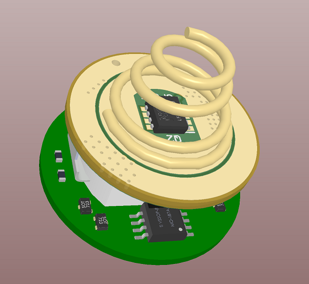
At this point if you were following me closely, you would have thought to yourself - "but don't you need a source for the gate voltage to trigger the FET?", and you would be right. To make this work, I could stuff a coin battery in somewhere, or a supercapacitor. But the former was too big, and I really didn't want to have the trouble of replacing batteries, and the latter was either too expensive, or had insufficient capacity in the physical size constraint.
Turns out though, people make really tiny rechargeable lithium batteries! So this is what I've used. These are used frequently in low-power systems where the battery might be used for RAM backup in the event of a power loss, or for energy harvesting etc. So on the PCB, I have a tiny rechargeable battery, with a small voltage regulator which charges the small battery from the main 18650 cell when the light is turned off. In order to fit a bigger battery, I made a little slot on the top LED PCB. So that's what the slot is for
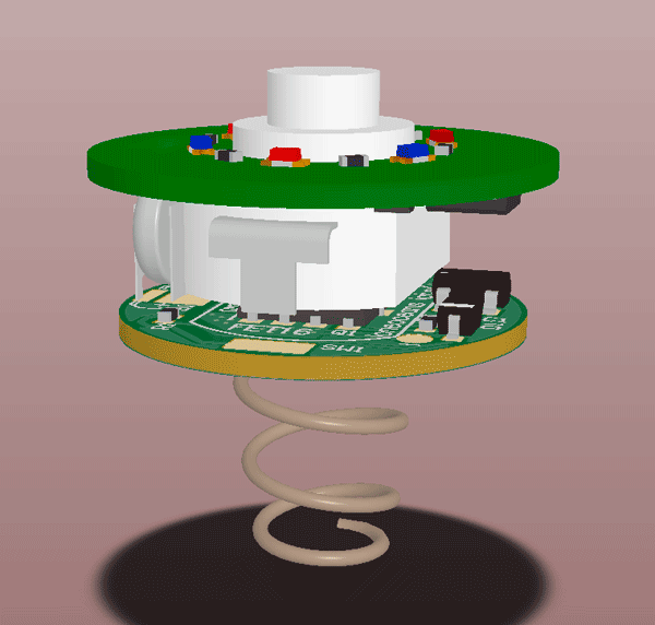
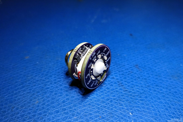
Here's how the two boards look like:
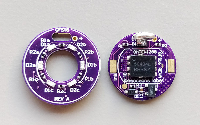
Shown here with the FET and no switch soldered on yet, so you can see what's going on.
I didn't know what to call this project, so I've just used a similar naming convention to my GXB project, and I've called it the GFS16 system, where 16 stands for the nominal 16mm diameter, and FS stands for FET Switch, or Fancy Switch, or Frivolous Switch, whichever you like ! The Fet board is 16mm in diameter and the LED board is 18mm. The hole in the middle fits the standard Omten1288 switch.
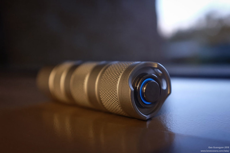
With the PCBs soldered up, here's a quick series of photos showing one assembly I did with a Convoy S2+.
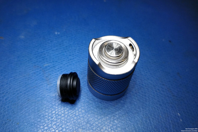
First up, I changed the black tailcap switch with a stainless-steel one with a clear rubber boot. This allows light to shine through so we get the lighted tailcap effect.
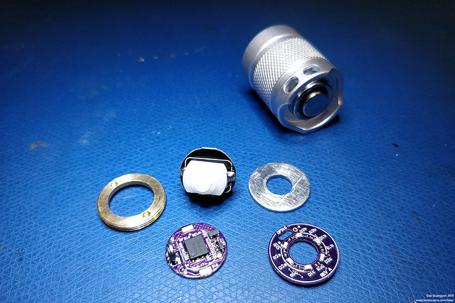
Next, I disassembled the tailcap. Notice how the LED ring replaces the aluminium washer, and the FET board replaces the stock switch PCB. I then desoldered the spring and Omten switch from the stock PCB. You could just use a new Omten Switch but I had no spares lying around.
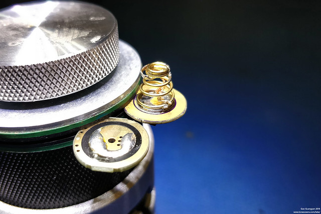
The spring as well as the switch were soldered onto the new FET switch PCB. Note that I kept the solder-wick spring bypass. No point saving 20-30mR in our switch and losing it all in the spring!

Finally, it all comes together! Power to the LED board comes from two small wires from the 16mm FET board. You can see the + and - pads in the PCB photos above.
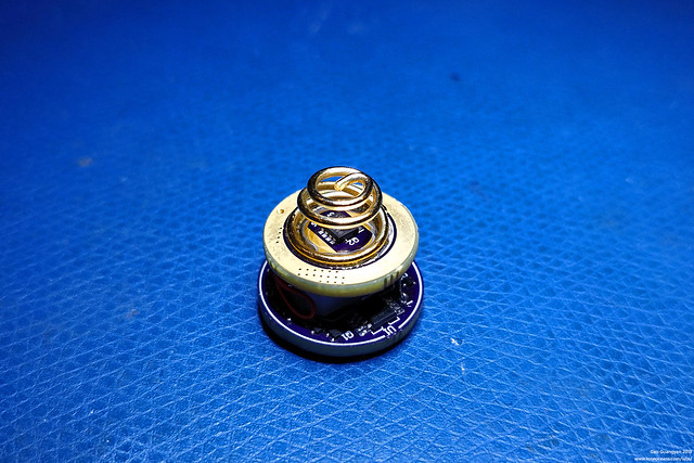
Here's a completed tailswitch with additional pads, allowing for a LFPAK33 FET to be soldered on in the middle of the battery spring. For this configuration, a larger spring like the Noctigon Beryllium Copper springs work great.
Here's a video demonstrating how it switches LEDs when the voltage drops!

Alright that's all for today. Turned out to be a fun little project. Best of all, it actually seems to work great with my GXB172.
So again I'm not sure if there's any product like this out there, but from my previous projects, it seems like maybe some people would want to build their own as well.
[Update Aug 18]

Updated the LED board for even better stand-by current draw performance. Fady, Lexel, etc helped with some good feedback so I spent a half hour doing a quick update, replacing some components with much lower quiescent current ones. The result is an order of magnitude less current draw! The result should be a ~12x longer standby time after LEDs turn off, and a ~30+% longer shelf time with LEDs on.
No thought was given to optimize for cost, so the parts are a little expensive, but that's ok I think since the absolute cost is still decent ^_^. Feel free to sub for cheaper alternatives!
Above is the Rev B of the LED board with much better standby current characteristics. This was measured at (5.6+-0.1)uA at 3V battery voltage.
FAQ
- Where can I buy this? Are you selling this?
Why would you want to buy this from me and give me money when... you can just order the PCB yourself! I've uploaded the files on OSHpark, and I'll be writing up a page with more details soon. If you're interested in ordering your own, note that I recommend ordering the right thickness to suit your needs. If you're using Rev A of the FET board with a fet under the switch, I recommend ordering 0.8mm thick versions. With Rev B and using the FET inside a big spring on the FET board, 1.6mm boards are fine for both. You might have to shim the switch for best clicky performance.
- Do you have a parts list?
Please scroll down for the Parts List and PCBs!
Note that while the board can be assembled at home, it does have fairly small SOT723 and 0402 parts, so you'll need a very small tip soldering iron, needle tweezers, preferably some magnification, a bit of patience and a whole lot of flux. Good luck! Parts list are at the bottom of this post!
- Can you make one for me?
Unfortunately probably not, as much as I would like to help you out. However with a bit of practice it's not too hard to assemble one yourself. :) I recommend ordering many more of the SOT723 fets than you think since they're the hardest ones to solder here.
- Will this work in my flashlight?
I really have no idea if it will fit or not unfortunately. I designed this specifically for my Convoy S2+, so if you have one too, it should fit.
- Are there any known problems?
Yes! At least for the LED board (Rev A), when the voltage drops below ~2.5V+, we are out of spec for the comparator, so it might stop working and the red LED may come on again dimly. You will run the danger of depleting your battery, but I suppose this is no different from a regular lit-tail cap, but at least slightly better since it extends the 'safe' shelf time. This is improved further in Rev B which works all the way down to such a low voltage that your battery would be really dead before this happens.
- Will this work with ___ driver?
This seems to work just fine with my GXB172 driver with no modifications, but I hear some drivers need a bypass resistor. I have no such drivers so I've been unable to test them, so your result may vary. A lower value bleeder works best but at a cost of increased wasted power. See next question. Likewise, different drivers have different architectures, so it may mess with the battery charging circuit. Likewise, I suspect the resistor divider values will vary depending on the driver you plan to use, so a bit of experimentation is key to determine the correct resistor divider values.
- What bypass resistor value will I need for my driver?
As mentioned, I'm not sure, but definitely the lower the value the better, at the cost of reduced efficiency when the light is operating (since the resistor is just burning power). Typically values between 100 to 1000 ohms work well. At the worst-case scenario of 100 ohms, the resistor will burn about 176mW, so pick a resistor of at least 1/4W rating. I've used 220, 330, 560 and 1kR across regular Convoy S2+ drivers and they seem to work just fine.
- How long can the light be turned on for when using the GFS16 FET switch?
Good question. This depends on the capacity of the tiny rechargeable battery used. For small switches, a 1mAhr battery is all that fits. With a 1M resistor on the gate-source, the battery should technically last on the order of ~12 days, which should be far longer than the main cell will last for! If there is more space, you can swap it out with a ~3.5mAhr battery instead to get more battery life. The battery automatically recharges when the light is off and the cell voltage is sufficiently high (nominally >3.5V).
- Can the FET16 switch be used without the LED board
Yes!
- Can the LED18 board be used without the FET board?
As long as you make the right connections (+ to flashlight body and - to spring), yes!
- Will there be revisions to the board(s)?
I'm not sure, probably though. I designed all these boards in half a day so... probably I'll find things to improve. Writing this post took about as long as making the boards. Whew! Suggestions and feedback are welcomed!
OSHPARK PCB ORDER (recommended to get Rev Bs)
Recommended to order in 1.6mm regular PCB for Rev B, or 0.8mm 2oz is ok as well - make sure if fits your host stackup! Tested to fit for Rev B PCBs in 1.6mm thickness and Convoy S2+. YMMV for different hosts.
Again, each board works just fine as standalone!
18mm LED Board Rev A: https://oshpark.com/shared_projects/GtiA9PQQ
18mm LED Board Rev B: https://oshpark.com/shared_projects/L27QGJFW
16mm FET Board Rev A: https://oshpark.com/shared_projects/U2bESKnQ
16mm FET Board Rev B: https://oshpark.com/shared_projects/dwoKK9Uo
- Added dual FET footprint, you can now use a LFPAK33 FET in the middle of a big spring, so you can also order a regular 1.6mm thickness PCB :)
PARTS LIST
If you're reading this, you're planning to put together your own board. It's pretty easy, but do keep in mind that some of the components are very small, so this is best done with some magnification, needle tweezers, very fine solder wire (this is very important! Use 0.015"/0.40mm solder wire or thinner), and a fine soldering iron tip. Good luck!
LED18 Board with Battery Voltage Sensing BOM (REV B)
- R1a,R1b,R1c - 30kR 0402
- R2a,R2b,R2c - 12kR 0402
- Q1 - RZM002P02 or any other SOT723 P-Fet
- Q2,Q3 - NTK3043NT1G or any other SOT723 N-Fet
- D1a,D1b,D1c - Blue 0603 LED 150060BS75000 or colour of your choice
- D2a,D2b,D2c - Red 0603 LED 150060SS75000 or colour of your choice
- C1 - Any 10-100nF 0402 capacitor
- R3, R7 - 619kR 0402 resistor
- R5 - 470kR 0402 resistor
- R4,R6 - 1M 0402 resistor
- U1 - MAX6007BEUR+T
- U2,U3 - TLV3691IDCKR
Rev B now features 12x lower I_q for longer standby and remains simple with no additional bells and whistles.
3.32V low voltage threshold (R3 and R4, sensed with R4 as lower)
Since people are asking, I've also tested this board with a 560R bleeder resistor across a Convoy S2+ standard driver, with R3 = 681kR. This gives a 3.55V low-voltage threshold (hysteresis at 3.75V), which seems to be fairly practical for most people.
3.01V turn-off threshold (R5 and R6, sensed with R6 as lower)
Careful component placement so no components hit the shelf on the LED side. All resistors or 0402 in size (1 or 5% is fine), and all LEDs are 0603. You will need to wire + to the flashlight body, and - to the tail spring. Typically this is done with a switch PCB (see here https://budgetlightforum.com/t/-/32103), or you can pair this with the FET16 board like I've done. You can use as thin a wire as you like since the current is very low.
LED18 Board with Battery Voltage Sensing BOM (REV A, older version)
U1 - MAX9052BEUA+
Q1 - RZM002P02
Q2, Q3 - NTK3043NT1G
R3 - 115kR
R4, R6 - 360kR
R5 - 68kR
R1a,b,c - 30kR (or adjust for brightness)
R2a,b,c - 12kR (or adjust for brightness)
LED1a,b,c - Blue, 150060BS75000
LED2a,b,c - Red, 150060SS75000
Not that R3/R4 and R5/R6 set a voltage divider which is compared against 2.5V.
R3/R4 sets the first trip voltage. In this case, when the cell voltage is ~3.3V, the LEDs will change from Blue to Red
R5/R6 sets the 2nd trip voltage. In this case, when cell voltage is ~3.0V, the LEDs will change from Red to Off
Alternate values for R3 = 68k and R5 = 33k will result in a trip voltage of 3.0V and 2.73V respectively.
All resistors or 0402 in size (1 or 5% is fine), and all LEDs are 0603.
You will need to wire + to the flashlight body, and - to the tail spring. Typically this is done with a switch PCB (see here https://budgetlightforum.com/t/-/32103), or you can pair this with the FET16 board like I've done. You can use as thin a wire as you like since the current is very low.
FET16 Board - works together with LED18, or standalone if desired
Spring - Noctigon Beryllium Copper spring is great (http://www.mtnelectronics.com/index.php?route=product/product&product_id=385)
Q1 - Any suitable PowerPAK SO8 or SO8 NFET
I've used a SiRC16DP or NVMFS5C404NLAFT1G - these are totally overkill though!
Here are some options on Mouser
Q2 - Any suitable LFPAK33 NFET
I've used PSMN2R0-25MLDX, but any here on Mouser should work fine.
* note: you only need to solder on either Q1 OR Q2, not both. FETs should have low on resistance at >2.7V V_gs for best performance
SW1 - Omten1288 (Mtnelectronics or Kaidomain)
D1 - Any SOD323 diode like https://www.diodes.com/assets/Datasheets/SBRT05U20S3.pdf
R1 - 2.2kR 0402
R2 - 100R 0402
R3 - 1M 0402
C1 - 2.2uF (0402, 10 or 16V X5R Ceramic)
U1 - AP2210N-3.3TRG1
B1 - MS412FE-FL26E
* note - this small rechargable battery needs to have its soldering legs carefully cut-off, and then soldered standing vertically upwards as shown in the images above. This may be tricky to do. Use sharp flush cutters to cut the tabs as close to the diameter of the battery as possible. For soldering, I typically wrap the battery in kapton tape then hold the battery with a pair of needle nose tweezers (tape to prevent shorting out the battery), and carefully solder one side first, then the other, onto the PCB pads. Do check that the battery is not shorted out, and the polarity is correct.
* note 2 - IF you have more space and you use the Q1 option, it may be possible for you to fit the larger MS518SE battery in.
* note 3 - you might need to add a driver bypass resistor (see here https://budgetlightforum.com/t/-/32103) to allow your driver off-time memory to work, depending on the driver. In addition, ensure that sufficient voltage reaches the tailcap so the rechargeable battery can be charged from the main cell. Typical bypass resistor values of 470 ohms to 2.2k ohms should work.
As always, thanks much for reading!
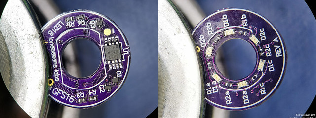
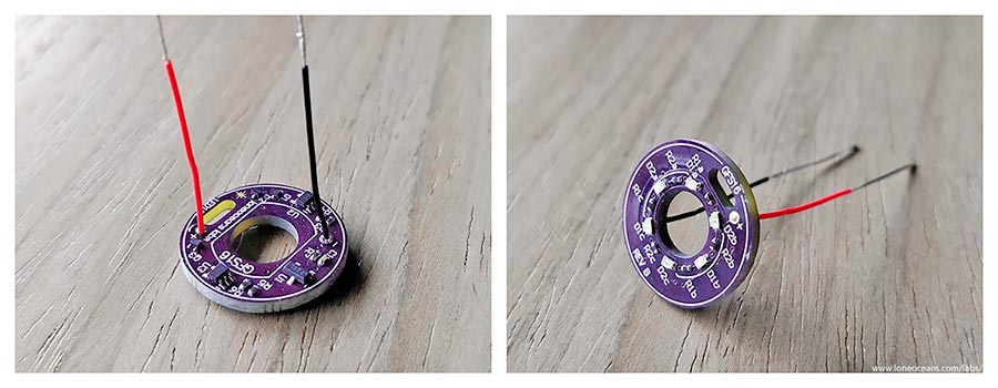
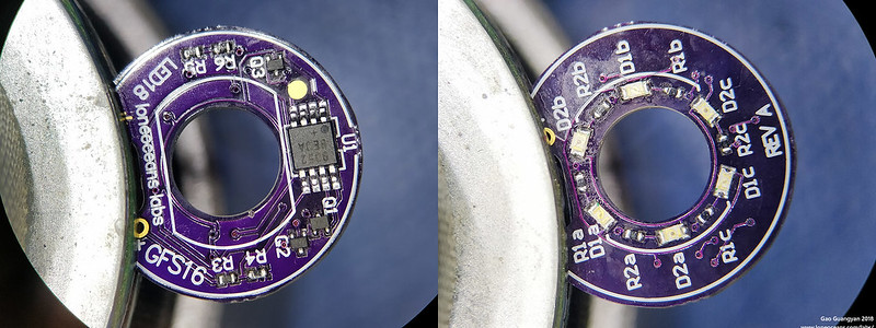 Finally, above is a clear view of the GFS16 (LED 18mm) board with components soldered as a reference for people trying to make their own. The BOM is updated in the OP. With the default resistor values, BANK 1 of LEDs turn on when V_bat is >2.97V, and changes to BANK 2 when 2.73<V_BAT<2.97V.