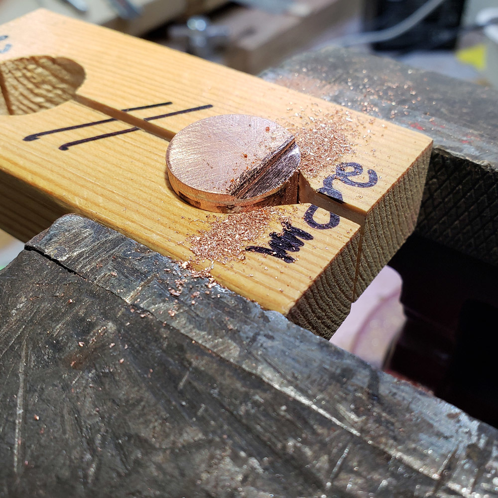
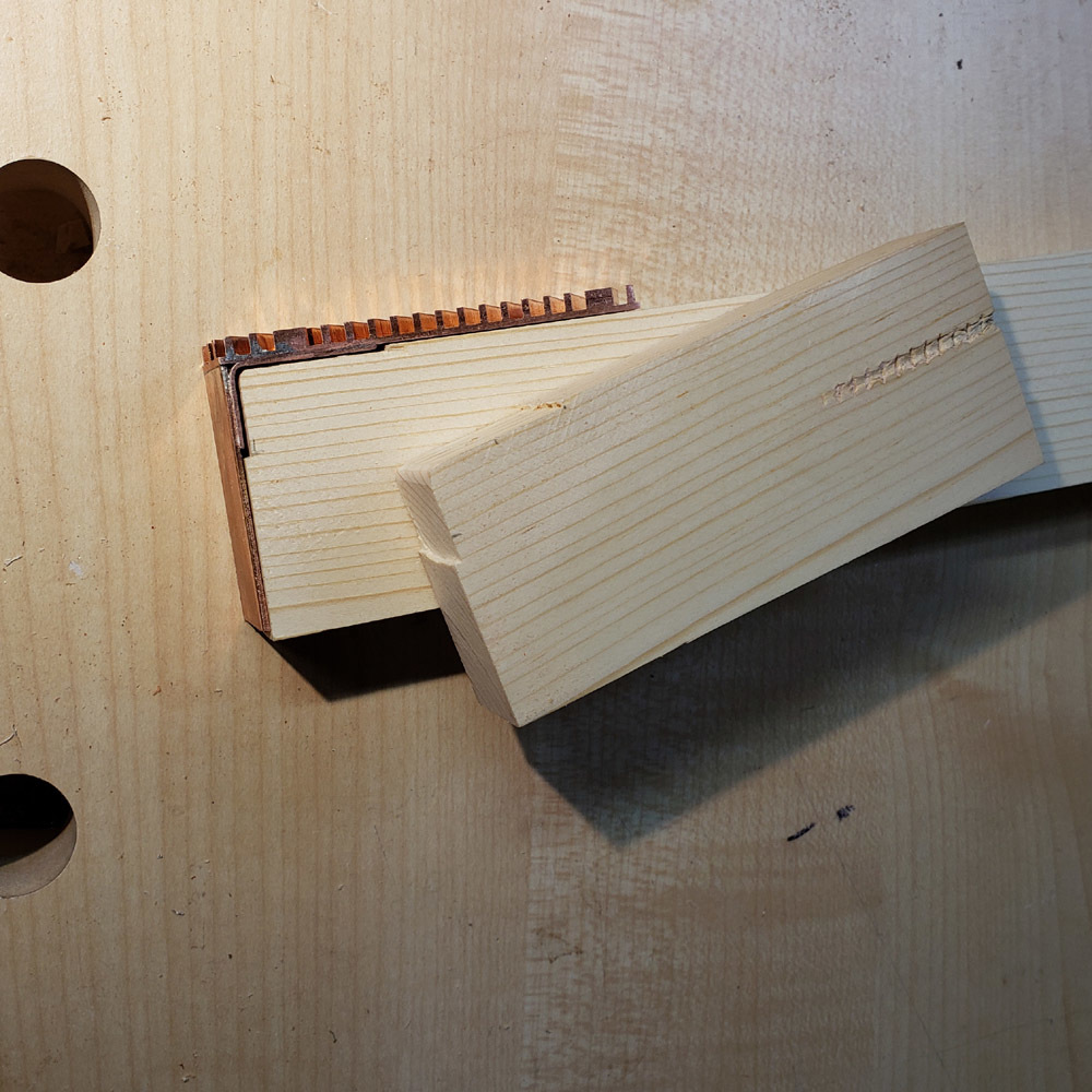
I decided that since the saw was still set to the 19.9something mm width I would cut another piece of pine in case I made an error and had to redo the inside block.
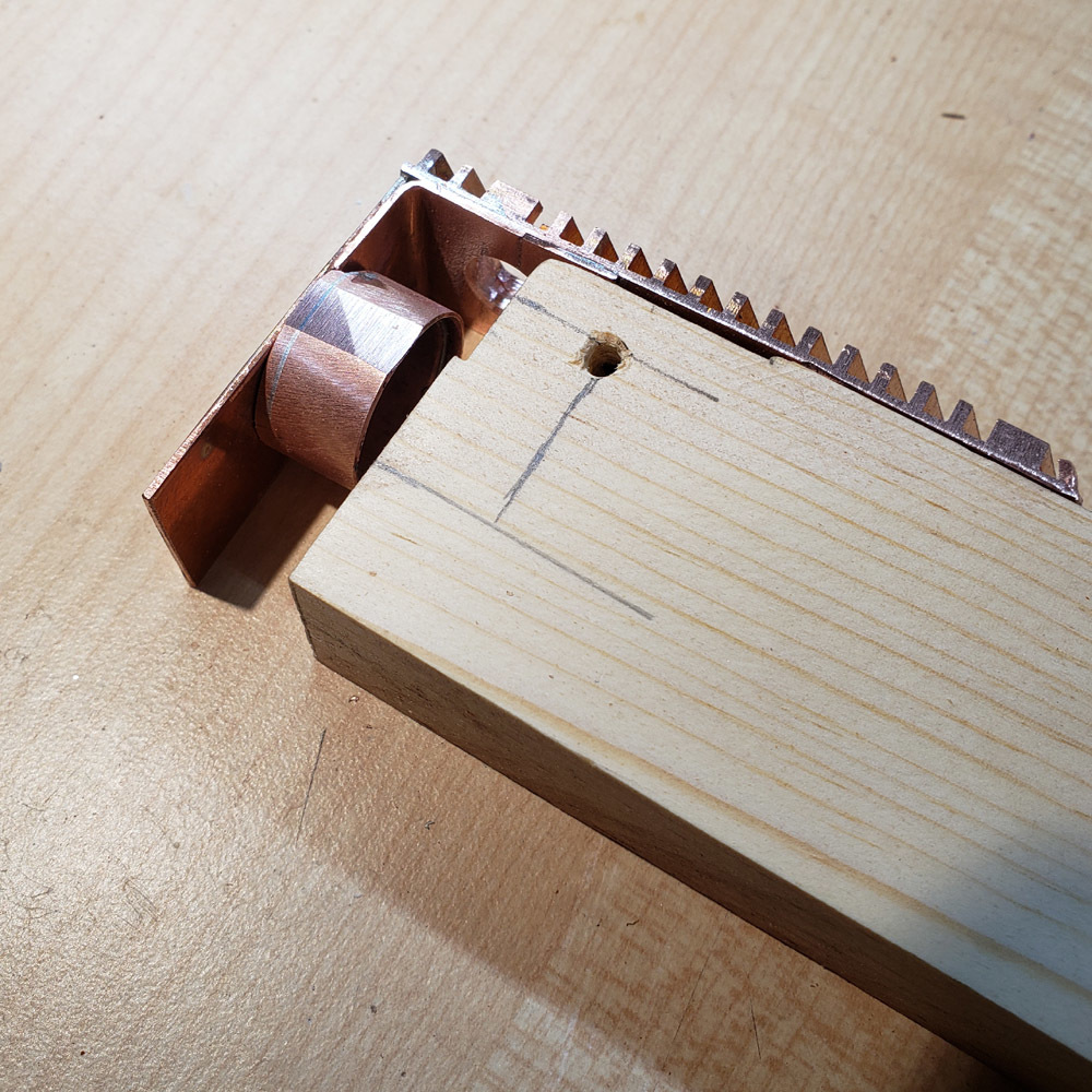
I also picked where the switch will be mounted and drilled a pilot hole in the copper heatsink at that spot. No picture of that drilling, but here is the result in the copper heatsink. Plus the new wood block with one corner rounded and notched as in the first trial piece.

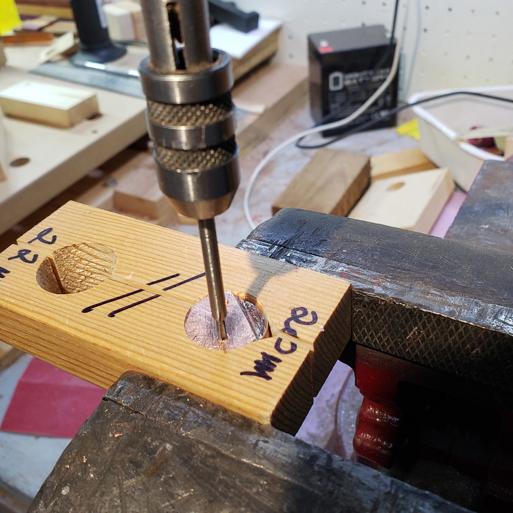
I used the pilot hole in the copper heatsink to mark the switch position in the wood blocks.
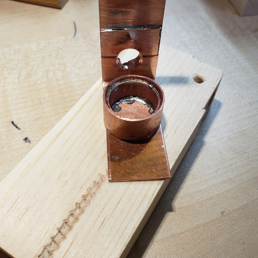
Then the hole in the heatsink was bored larger to fit the silicone boot that will be used.
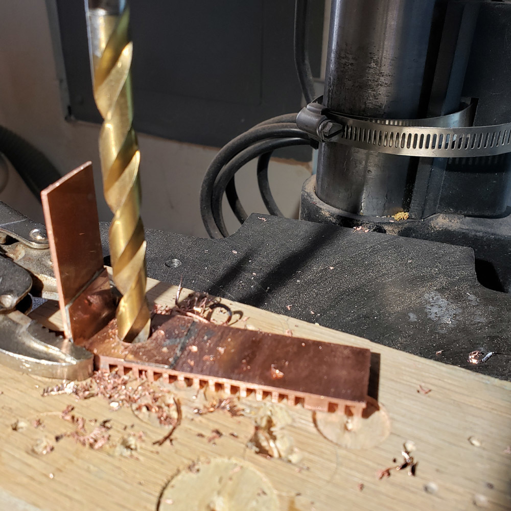
I de-burred the underside using a countersink bit.
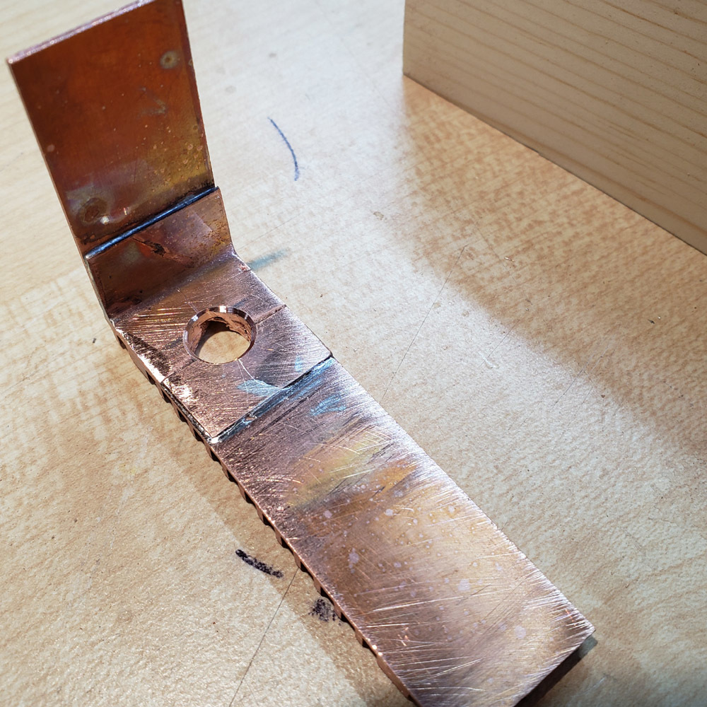
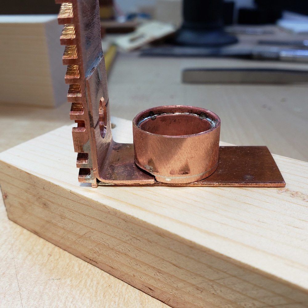
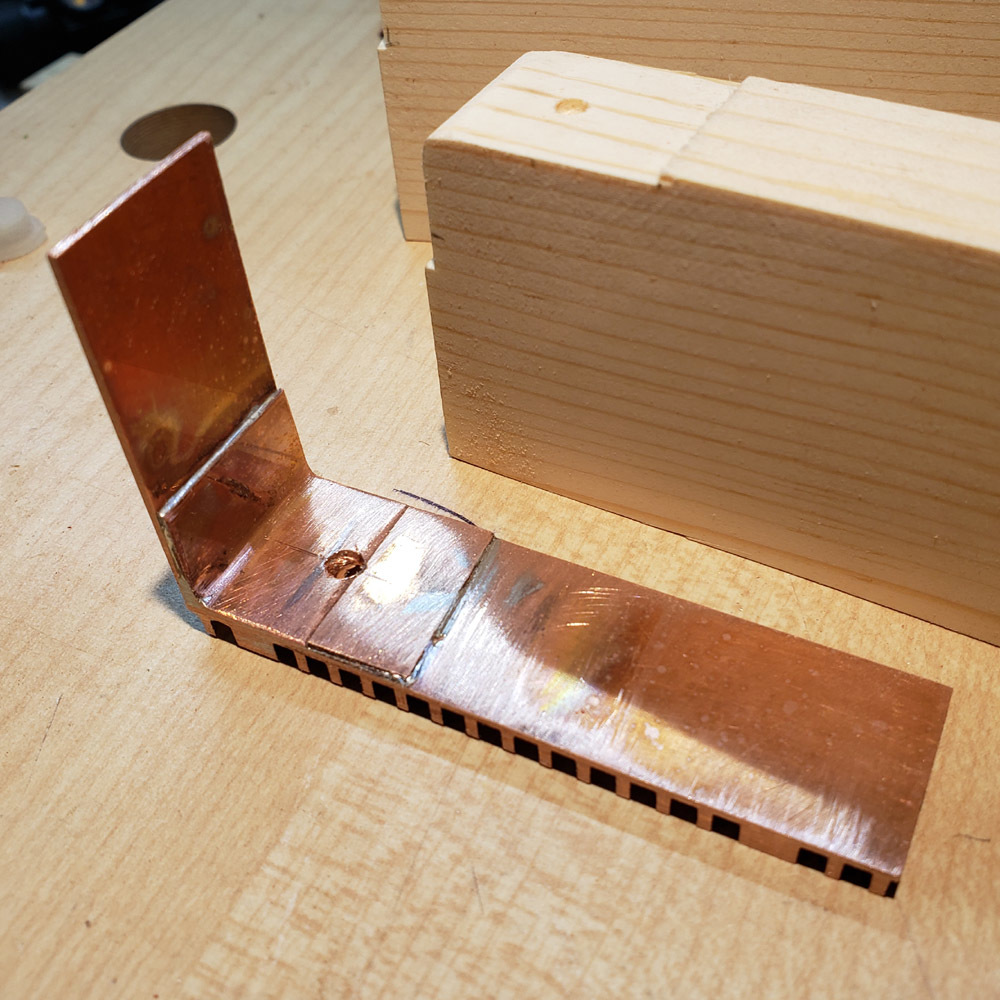
Note that the position of the switch necessitated soldering a small piece of copper sheet adjacent to the angle piece that was used to join the heatsink to the flat copper strip. This was done to even out a large enough area for the switch boot to mount securely.
The finned side came out a little messy. I thought that would happen. However, I believe attempting to drill into the finned side would have been more damaging.
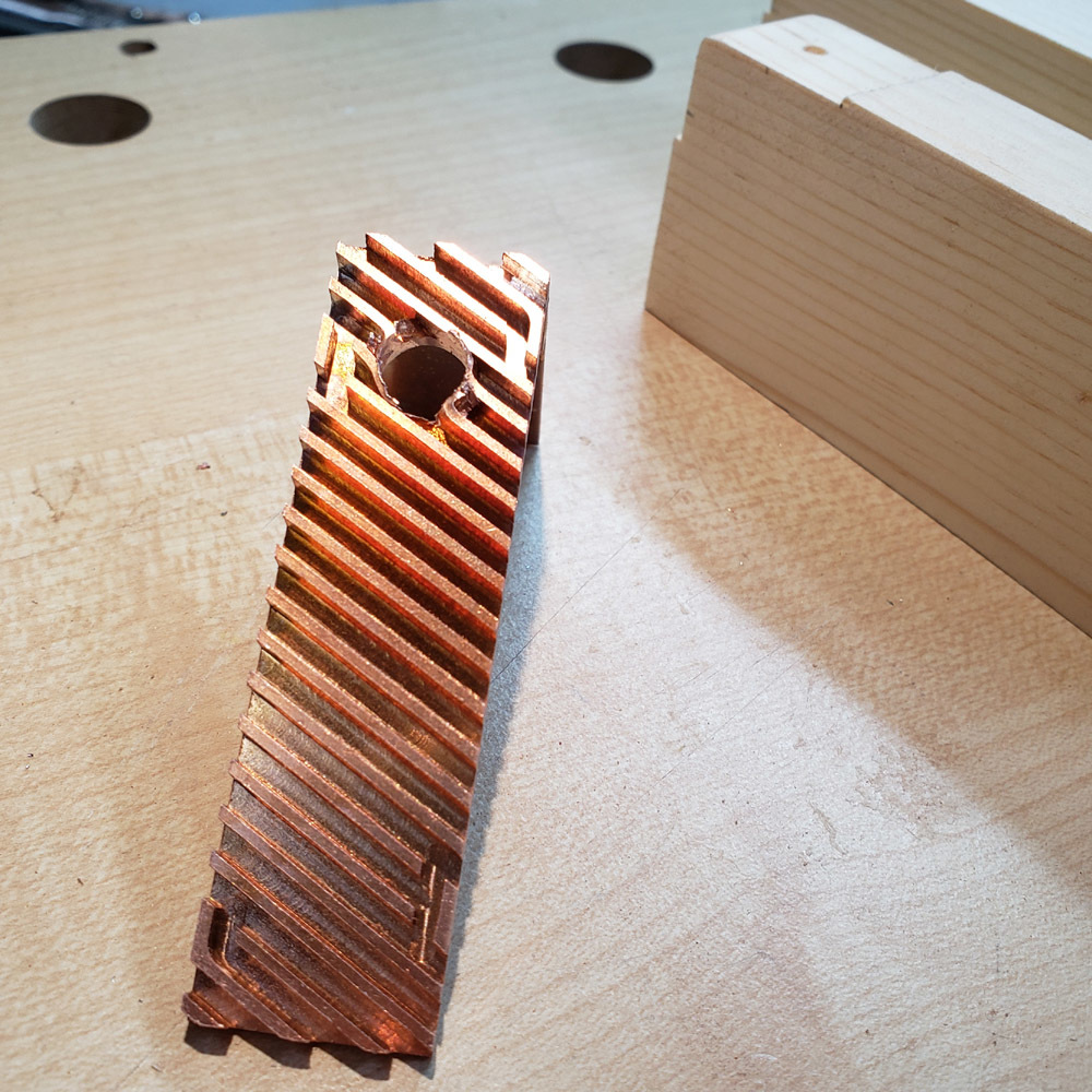
I clamped the block in the vice and secured the heatsink assembly to that with a clamp. Then I cleaned up the fins with a small file.


This is the momentary switch I am using. It is from mountainelectronics.com. Also pictured is the switch boot I will use. The assembly needs a spacer, a “nub” inserted under the boot and over the switch activator button. I cut a tiny piece of pine for the task.
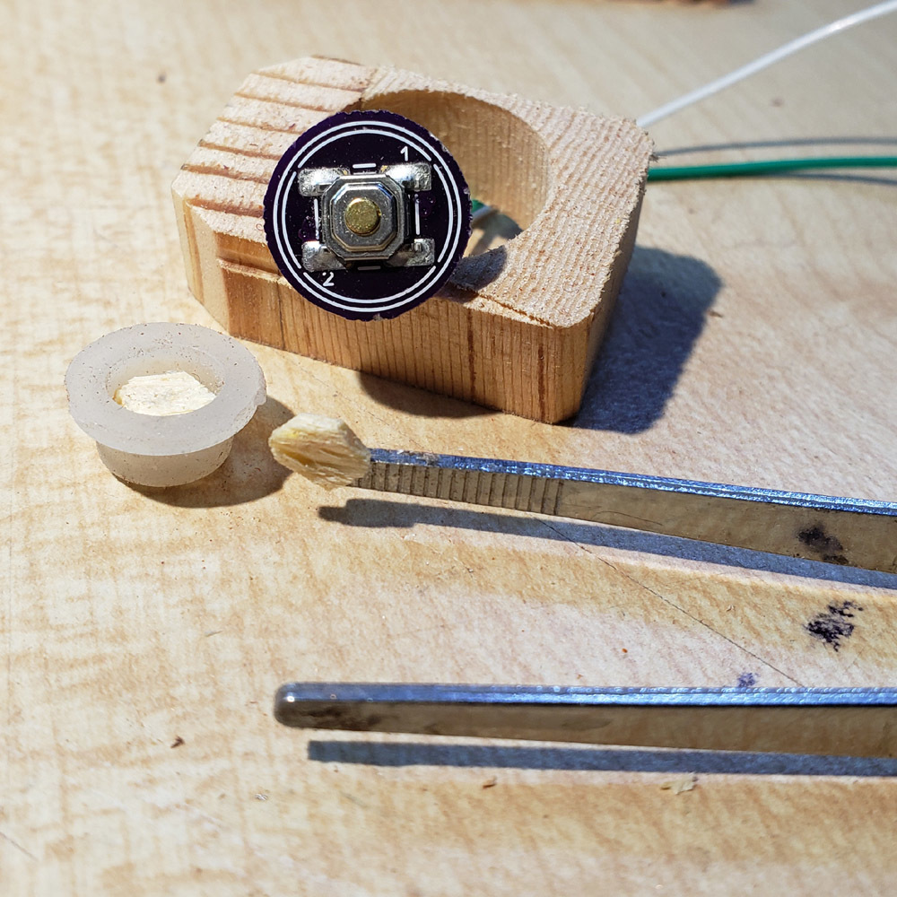
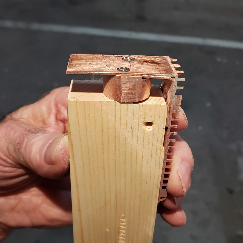
I drilled a 2mm deep recess in the top surface of the block to hold the switch ans boot. The switch and boot are held in place when the copper heatsink assembly is placed on top. The switch wires snake out through a side hole I drilled.

When depressed the switch could be heard clicking but I thought I would verify operation. One image showing an open circuit and then with the button depressed the circuit is completed.


More in the next post….