If you want to learn how to do the LED swap yourself, here is a photo album showing the process:

You can also hire someone to change the LED for you.
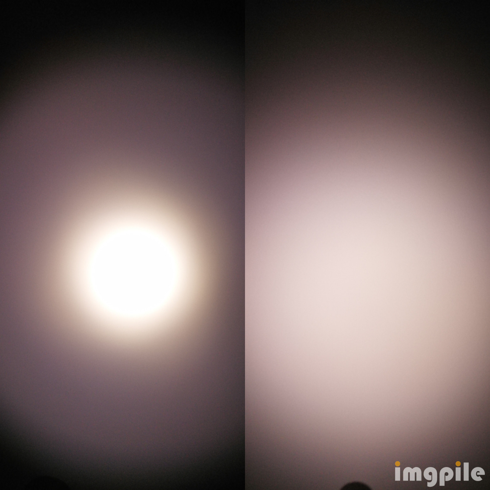
It is not very pink… here is the difference
Dome On:
 .
.
Dome Off
 .
.
If you want to learn how to do the LED swap yourself, here is a photo album showing the process:
You can also hire someone to change the LED for you.
It is not very pink… here is the difference
Dome On:
.
Dome Off
.
Jon, I don’t share your experience
This was my result dedoming 4500k
Locked to 4500K but in person it was that pink. Entirely too rosy for me
Thanks for the photo. You might like 519a 5700K Dome On (on left) ![]()
 .
.
Here is Opple comparison of the 519a 5700K compared to daylight where I am. You are located 30 degrees closer to the equator. That may be part of the reason we like different tints ;-):
 .
.
Sounds like you have a defective unit. Note that it might not be the tailcap. It could be the back of the tube is too short.
It might be a good idea to test to make sure that the tailcap contact is the problem.
Assuming the contact between the tailcap and tube is the problem, rather than returning it, there is a simple fix:
This fix should solve the problem and give you a working light.
Thank you Jon_Slider, great information there but looks quite daunting to me! I could pay someone I guess to make one for me, but including the astronomical postage from the USA, I think I will have to make do with my poor cousin version I have put together using Lee Zircon filters…
I agree with this. There is not many competition for a shorter version with dual fuel AA/14500 lights.
Anyone have a link to the source code? I can find the hex but don’t want to decompile just to look at the source and see if I can modify the code
I think so? This is my first attempt at editing code and compiling. Looking at the notes on the page it seems the latest revision would work for the sp10 pro.
Stupid question, but: is there a place in the SP10 Pro driver to which we can add some wires to control aux leds like the ones in the TS10 MCPCB?
Thanks in advance ![]()
There are no extra pads, you can solder directly on the pins with thin magnet wire but it’s meticulous work. I’ve already done it while debugging drivers. Using a corner pin is less difficult.
Of course: the microcontroller itself. Just add a LED with a resistor to the appropriate pin. Well, soldering to it might be difficult. ![]()
Thanks for thre reply, thefreeman :+1:
Hum, when you are said the pins, which ones should I be aiming at? Also, how thick/thin, show the wire be?
I am not sure if am fit for these adventures but…I guess I would try since I have some spare material!
Both pins on the bottom right corners (15/PC0 and 16/PC1) appear to be free.
Something like 32AWG or smaller, the enamelled wire I use is 36AWG
Thanks SammyHP!
Hum, getting the resistor is probably harder for me (although I am not pro in mircosoldering ![]() )
)
But, again, I might try it :innocent:
Thank you once again for the reply and “directions” ![]()
I will see what I can get and do ![]()
If I succed, I will post it here !! And if not…I will post it too ![]()
A reference from the datasheet for those of us who are not intimately familiar with microcontrollers:

This may be handy, thank you contactcr ![]()
Hum…well, when I got home I went to check the spare driver I have and…I guess I would fail completely to solder such thin wires there :o
That thing is tinier than I could remember and my skills and iron and not fit for the job after all ![]()
So, I will pass this possibility ti have an SP10 Pro with aux leds. For now ![]()
Thanks for your replies folks ![]()
All pin 16 17 and 18 look free, so you could solder a wire without caring much about solder brides between those pins.