So I finally got around to doing the "simple" emitter swap on my Trustfire F20. I'm planning an XM-L U2 1C for it. Right away I saw it was going to be harder than I had expected! Emitter was glued down really well and was very hard to break loose. Then after I got the emitter off the positive wire dropped down inside the pill! So then I fight to fish it back up through (yes, I actually got it back up through!) and it breaks off the driver board! Argh! I’m ready to scream at this point! So I fight like hell to pop the driver board off. I was pushing it out through the front side using an ice pick through the LED wire holes.
I got it off finally and see it was soldered on the inside (how the hell did they do that???). It's a 2 board setup - battery contact board and actual driver which apparently just floats inside the pill as far as I can tell. I can see where the positive wire connected, but I can’t find where the negative connection is made from the battery contact board to the driver board. So I go ahead with replacing a new positive LED wire and the trace rips off the circuit board! I ended up soldering the wire to the next contact over (coil) which seems ok as it seems it was a direct connection to the old contact point.
So my question, how is the negative (ground) connection made to the driver board? I'm thinking I'll need to add a jumper wire from the battery contact board to somewhere on the driver, but where? I plan to resolder the battery contact board on the outside of the pill like a normal human being would.
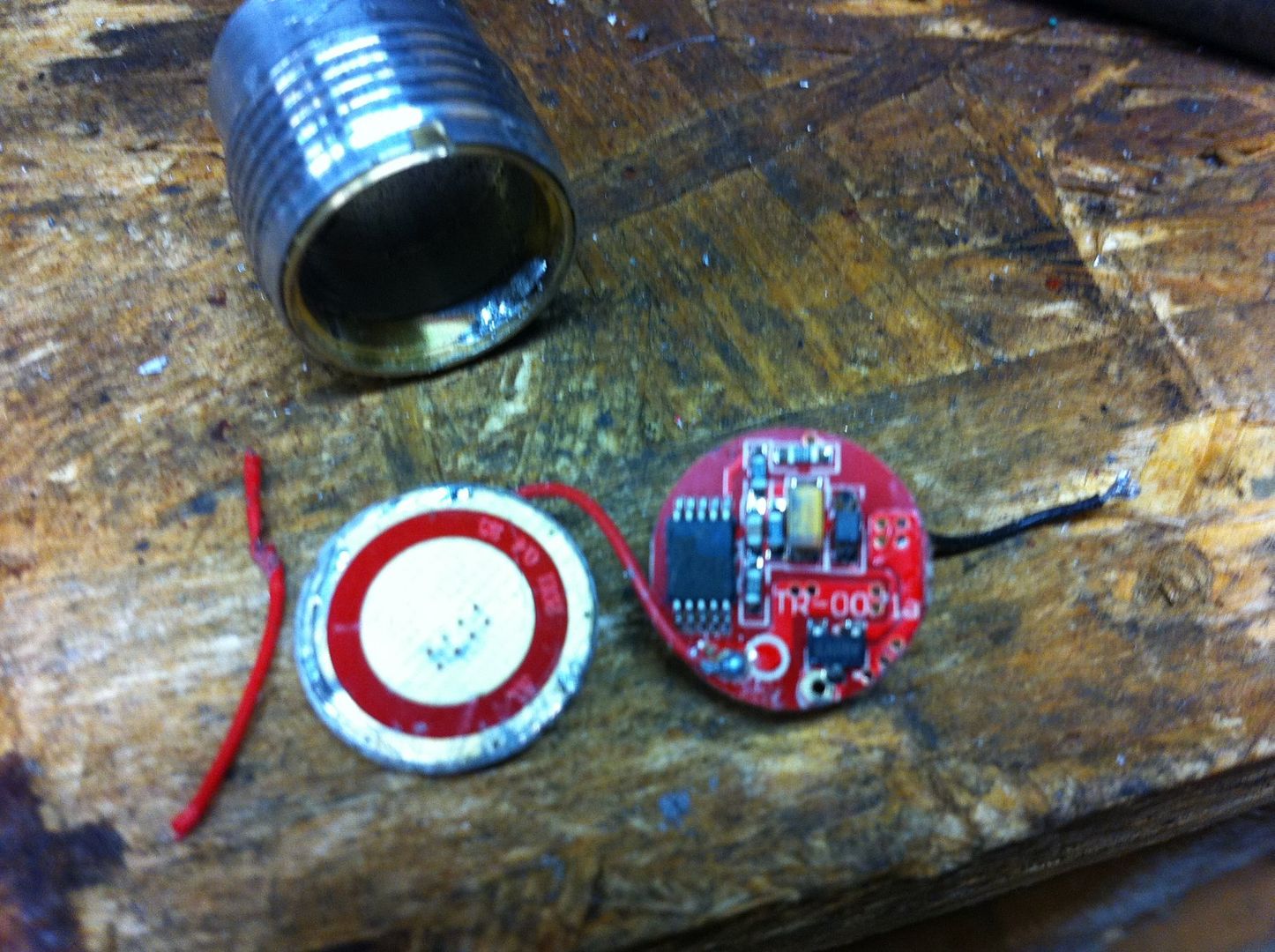
Here are some photos. (Sorry some are blurry - they're taken with an iPhone which doesn't do close-ups well.)
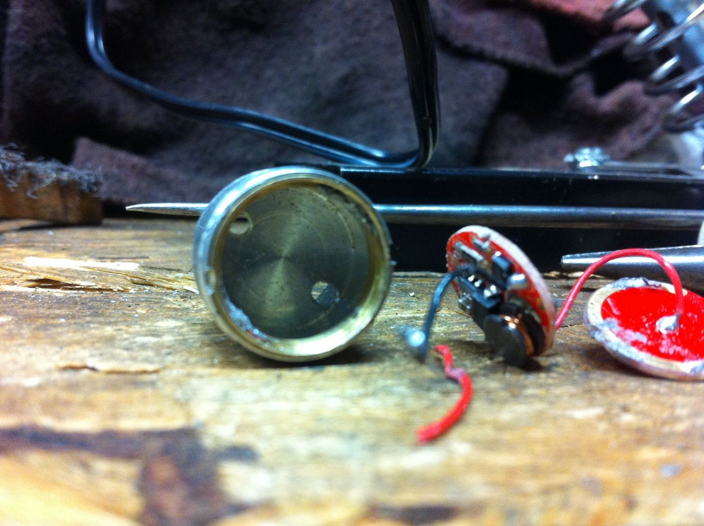
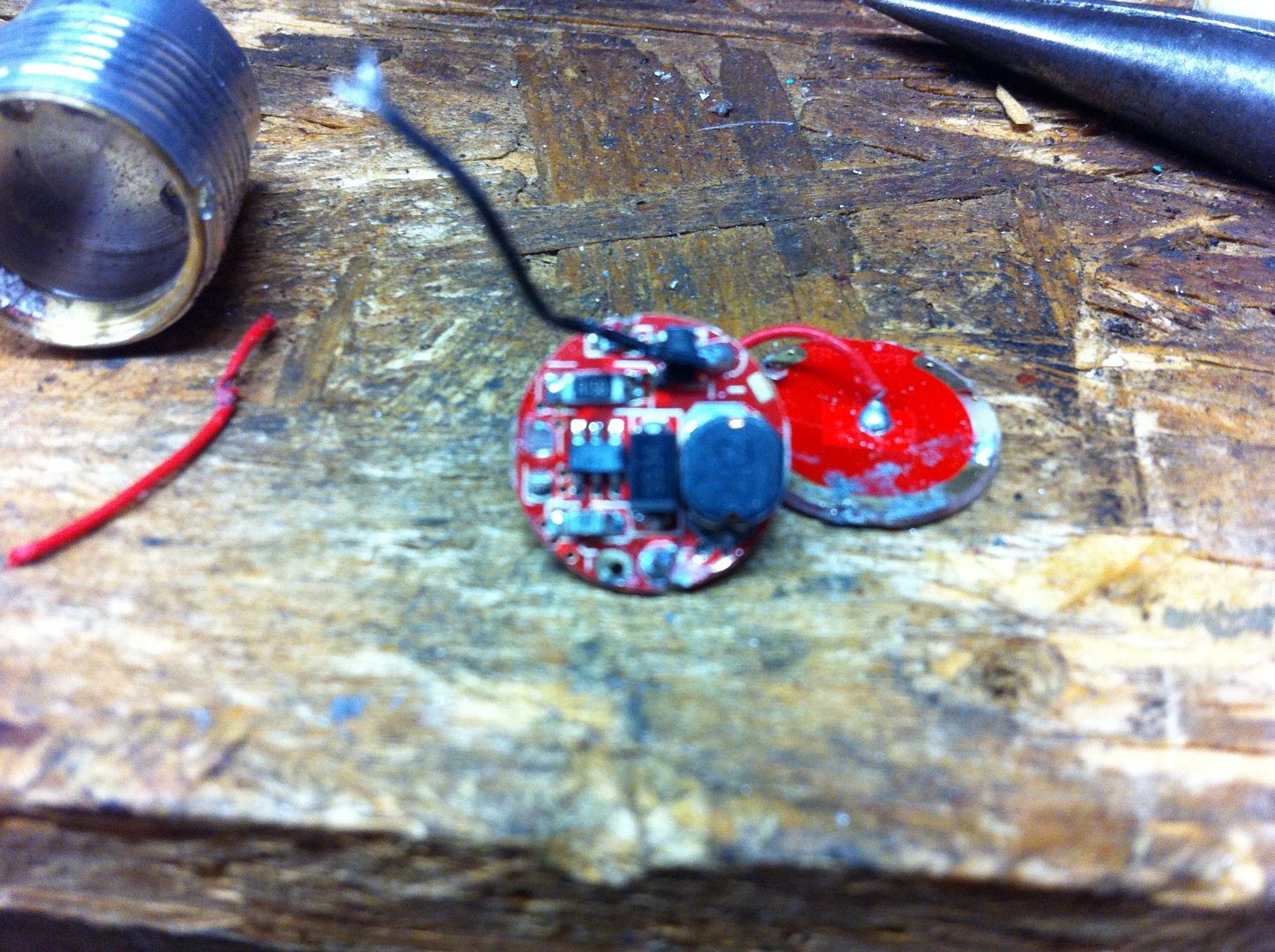
This photo above is the one I need a negative lead contact identified. Sure looks like it would be the golden colored solder pad at about the 4 o'clock position, but nothing looks was connected there when I took the driver out and I don't want to assume that's the correct location. No leads came out when I took the driver out so it seems original contact was made from the pill somehow - I just can't see how. This is why I believe jumping a lead from the driver board to the battery contact board is the best option.
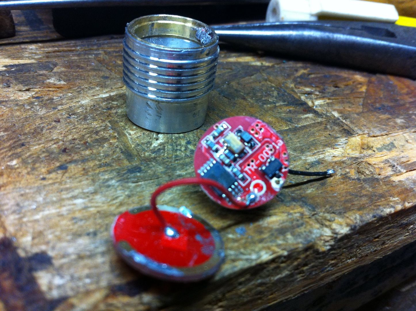
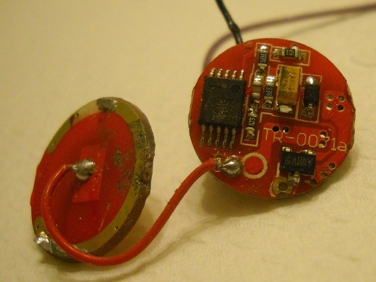
This photo above shows where I ripped off the positive wire trace off the PCB and soldered it over at the coil. This driver will definitely need a test with an alkaline first powering the old LED before I connect my U2 and put it in back in the pill!
Looks like there may have been a solid post(4mm long solid wire) at 1:00 on the battery board to the 4:00 hole on the driver. Just a guess though. Can you desolder the blobs on the bb and see if the remains of a post is there? Absent any post and given the length of the red bb wire, I’d go with a press fit driver soldered to the pill with the bb pressed in after and also soldered in. Also possible is that the boards were preloaded into the brass part and that was pressed into the aluminum pill.
I think you are right about them being fitted to the brass pill first before the brass pill was pressed into the aluminum, although the driver board does fit right through the brass ring (tight, but fits) and I don't see any solder on that underside of the brass ring. EDIT - looking over that picture again it does seem that perhaps that driver board was soldered to the brass pill at that 4 o'clock pad position, but barely soldered so as to break off really easily and not enough solder to fill over that "hole" on the pad. This is the only theory I have at this point and the only thing that makes sense.
I don't believe there was a "post" of any kind either. The section of the battery board ("bb") in photo #3 with the trace ripped off is where that board was soldered to the brass pill. That ripped off while I was poking the driver out. That pad connection on the driver at the 4 o'clock position doesn't seem to have had anything connected there.
Is there any way I can test with a meter or even with an alkaline battery connected to the battery board to see if using that 4 o'clock pad connection for ground is correct without burning up the driver? What's the worst that could happen anyway? Would I burn it up? I'm not going to get to this for awhile so I can hold off to hear all responses. I could even try to get better photos if needed.
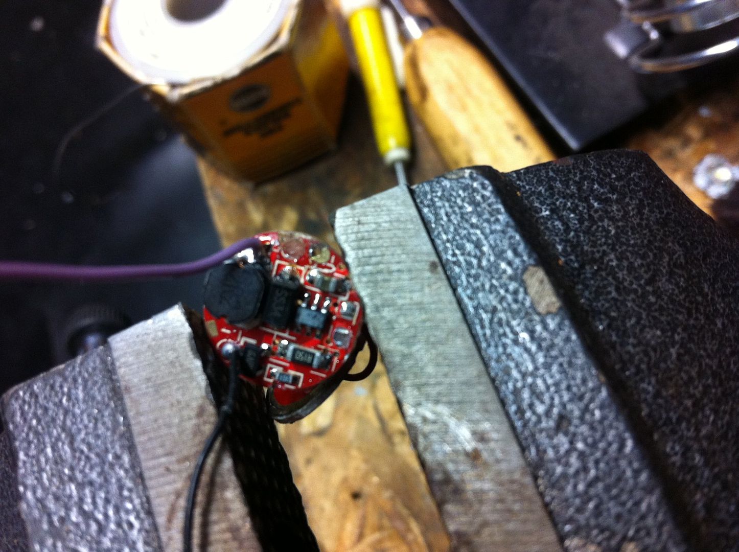
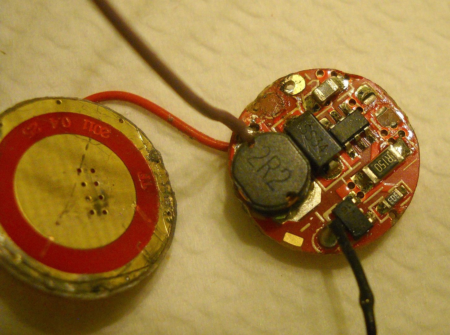
Suspect grounding solder pad at +/- 6 o'clock position:
Here on the backside (LED side) of the driver you can see where that solder pad is in relation to the positive contact that I ripped off the board by accident. If that is a negative contact it is awfully close to the positive!
Any idea what that component is in the first pic below the TR-0071A stamping? Would it make sense for that leg pointing down to be a gound pin?
Went out for pizza and MNF. That’s a good thought about that middle pin. Can you check to see if is at same potential as the proposed gnd hole/pad? ( 0 ohms resistance between them). If you find that the pad is gnd reccommend you reconnect the two boards with a post(like stacked driver boards) for the gnd connection. Then you only have to worry about soldering the battery board gnd to the pill which you can see. What are the other numbers/letters. All I can see is a “16”.
The driver should have been insulated you can do that with electrical tape. Your host is negative as is the pill. The opposite side of your contact board ( facing the LED should be your negative connection running to your LED. Put your driver in and hand press the contact board into the pill and make sure your wires and positive solder connections or blobs do not make contact with the wall of the pill. I use a thermal adhesive to keep the contact board in place then i solder it to the pill. If you have a Multi meter you can check to see if you have a short or a bad connection from the pill to the LED and from the negative on your contact pad to LED.
I have a brace of these for this very upgrade, one or two of which have been opened.
IIRC, I took pictures of this particular driver. Is yours the “5-Mode R5” or the “1 Mode Q4”? I can shoot the 5-Mode, but the 1-Mode is proving quite well impacted in the pill.
I’m on duty for the next few hours, but as soon as I get back to my dark place I’ll either dig up a photo showing where everything attaches, or just shoot it again.
Thank you for cutting first tracks down this slippery slope!! I’ve done the XM-L upgrade on a 5-Mode one, but (fortunately!!!) didn’t have this problems. DID have problems, just not this particular one.
Well I've got the driver wired up to the old LED. I direct connected a 14500 LifePO4 cell to test the LED and verify I had polarity correct (I butchered the old LED getting it out). Now all I need is a photo of that driver to see how to connect my incoming ground connection (hint hint :) ).
I did some continuity testing and the "suspect solder pad" is isolated from the incoming positive. One thing interesting: see the solder pad below coil 2R2? That solder pad has no continuity to my suspect ground pad. I thought it would. Perhaps it is another LED ground output (see there is a "-" label nearby).
Well, not really. I get called to work sometimes, and I never know how long I’ll be gone… I really do apologize for leaving you Good People hanging!
On to business!!
I really did shoot these when I upgraded the LED. Somehow, I managed to lose them.
SO!
Yes, I Will Disassemble Mine! I will want your help, so it’s only fair I reciprocate.
Here you go:
I’m guessing that huge solder blob is your ground. Also, I’d like to know what “V-” is for.
This is as built. I didn’t notice the crooked board until I posted this picture! I have not yet found the courage to rip the boards out…
And just to be thorough (and to hopefully invite critique), the only soldering I did on the project:
Sorry about the delays, y’all. I hope this still helps somehow.
PS: I have not yet managed to open the pill of the single-mode F20. When I do, I have a recycled CW XM-L to go in it, to compare CNQ’s “NW” with “the usual XM-L” in the same form factor. Teasing, yes. I am looking forward to more exchanges as I screw up more flashlights. This one is disappointingly DIM for an XM-L replacing a “R5” which looked like an XR-E… Sorry - no hijacking! I will shoot the single mode when I get it open.
That’s true, but you’ll need to maintain the switch at some time, or live with the dimness and flickering. If you think ANY of this is hard, wait until you try to get that switch out!! Just unscrewing the tailcap - or removing a chip with your bare teeth for that matter - becomes trivial by comparison! (BTW: I would LOVE to find an upgrade for this switch/housing, especially if it’s IPX88 waterproof!!!)
Uh… Sorry. Never quite got that “don’t” business…
I used a plastic chopstick-sized prod to hold the wires in place while I melted the solder with the iron’s pointy tip. Yeah, it’s ugly, but it passes electrons!
Thanks Dim! Pics 2 & 3 aren't showing up in your post (although I can click them and see them). How'd you get that brass pill out? Mine wouldn't budge. Also looks like I don't need to worry about negative contact from the battery carrier since it's made from the LED side of the driver board.
Notice the scratch marks on the side? Take a #0 flat screwdriver, jam it into the little notches you use to unscrew the pill, put another band-aid on your other finger, wipe off the blood, jam harder & twist. PCB moves <0.1mm. Do the same on the other side. Buy stock in Band-Aid. Repeat. Nothing to it!
Edit: I’m sorry, that was silly. You’re using one end of the edge of the screwdriver to carve a notch in the brass pill, then twisting the blade so as to push down on the Aluminum shell and simultaneously up on that notch. Each step may or may not need its own notch. Forcibly pushing a screwdriver at your own hand will hurt quite a lot if you screw it up. YMMV, and a clever hand with a wee grinder could adapt a set of needle nose pliers to the task…
Thanks! But I'm comparing your first driver pic to mine and I see a component has ripped off my board (where ground contact to pill is made). Perhaps it's still attached to the pill, but if not I'll have order another F20!