So after some thought, I’m ready to do my first mod, which will only be a driver swap :bigsmile: . I got the Roche LS01 this past week and was a little disappointed in its performance. It’s a solid host, and I like the XM-L2, but it’s very under driven. Size wise, I took rough measurements and it looks to be 24mm. Does anyone know of a strong driver that would be suitable for an XM-L2 with a 2*18650 battery configuration?
Also, if any of you think there is a better or easier way to boost the current in what I already have, please let me know. If there’s a level below noob in modding, I’m there.
In your opinion, would it be easier to:
a. unsolder the wires from the emitter and use new driver with new wires
b. unsolder the wires from new driver and use wires already attached to the emitter
While the OP may not want a really high current driver, the linked one is only 3A. Offhand I’m guessing that the stock driver is outputting at at least 2A, maybe 3A. Do we know what output current the stock driver provides?
Also the LD-2C includes a 20.5mm contact board, so a 24mm contact board will be needed.
To solder the existing wires onto the new driver will need a fine tip and not alot of power, but to solder new driver wires to mcpcb might require an iron with a bit more power (25w+)
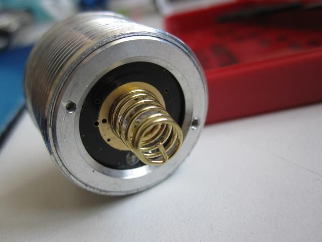
Unfortunately, I’m also the guy with stock leads on my DMM which can’t get an accurate current reading from the tailcap. I emailed BG before I ordered the light and he said it was 2.2A to 2.4A which I’m not sure of. Also, I’m currently using flattop Samsung ICRs so I would probably unsolder the copper spring from the old driver and put it on the new driver, if it’s possible.
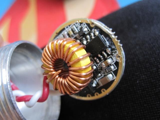
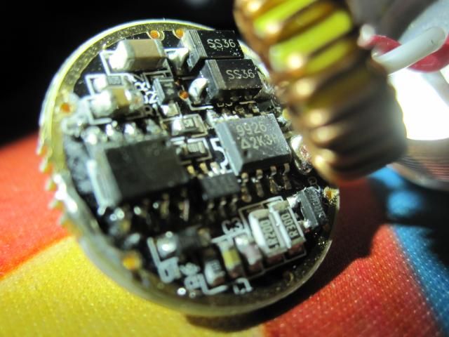
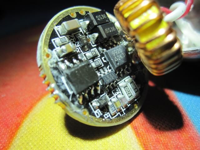
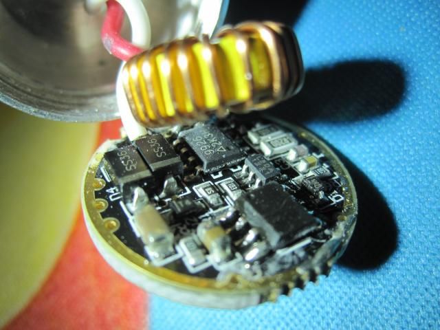
I’d consider resistor modding the stock driver. Would you be willing to gently bend the inductor out of the way and take a clear picture of the driver?
I’d be up for it depending on the level of difficulty. I’ll take more pictures when I get back from work tonight. What would resistor modding involve? Swapping resistors? Removing one?
You might have to get a little riskier to do the soldering.
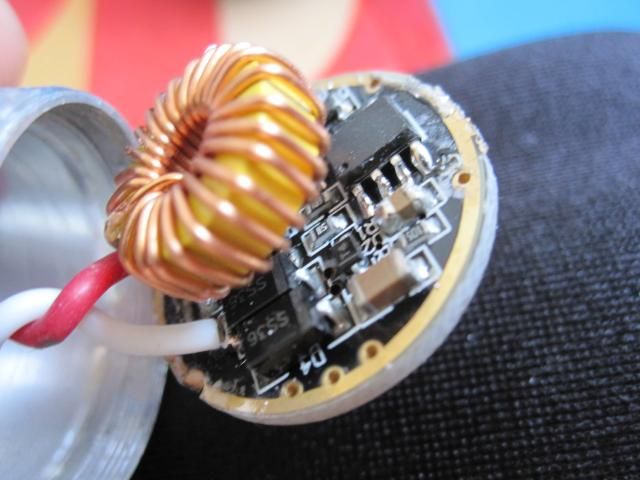
The two components marked R200 are your sense resistors. The R stands for a decimal place, so the markings are read as ‘.200’, which stands for 0.2 Ohms. They are wired in parallel, so the total resistance is 0.1 Ohms (calculator here). The buck controller is the common QX9920 (top-markings are LEDA and a manufacturing date code). It uses a “Current sense” voltage of 0.25v, but I believe it may sometimes tend to skew to a slightly lower voltage. If we plug the sense voltage and the sense resistance into this Ohms Law Calculator we find that the set current is _ (you fill in the blank here).
Adding more resistors in parallel will reduce the total resistance - play with the ohms law calculator in order to determine what effect this will have.
In order to work out a new set current you have two good options.
You can attack the problem from the set current angle (use the Ohms Law Calculator and punch in sense voltage + desired current) to figure out the needed total sense resistance. After doing that you must work out what resistors you need to add on top of the stock ones, you can do it by guesswork on the parallel resistance calculator.
OR you can start with some guesswork on the parallel resistance calculator (I suggest guessing along the lines of adding a single R500, a pair of R500, or a single R200). Take the results from there and plug it into the Ohms Law Calculator along with the Sense Voltage to see what those resistors will give you.
Remember, the circuit may not respond entirely linearly to your modifications so it’s best to be conservative to avoid damage. If you have the option to make a smaller change first and see what happens, do that. Please understand that you should never “bypass” the sense resistors. This will cause damage, period.
Thanks Wight. You’ve been a big help. From those two links you gave me, it looks like adding another R200 would bring the current up to 3.3, while another R300 would be 2.9. I’m willing to try adding another sense resistor. Do you have any links to show one would carefully add another sense resistor to a stock one? Is it simply stacking another one on top and then soldering the connectors?
Looks like you’ve got it figured out. [Now for parts sourcing. In the USA you may purchase top-notch sense resistors on Mouser or Digikey as well as some other vendors. Internationally I believe Farnell is the place to go. Or if you want to get it done on the cheap you can look at FastTech, they carry R120, R100, and R330 in the 1206 size. They also carry a bunch of values in the smaller 0805 size, which is not always an appropriate thing to use for big-current resistor mods.]
There are many, many discussions on here with pics of resistor mods like this. Sorry, I don’t have a link to anything that looks exactly like this. Here is RaceR86’s Supfire M6 resistor mod, note that these are actually 0805 sized. - Supfire M6 - resistor mod (Update testing XP-G2s on copper in post 59-60)
The stock driver is quite good, and you should try resistor mod it first before trying to find another driver. To get rough idea of its capability, bridging the sense resistors, I’m able to get over 4A (measured at tail) while driving MT-G2 emitter. If 4A is too high for XM-L2, then you can add/replace resistors to get the current that you want.
Bridging the sense resistors will instantly destroy an XM- or XP- series emitter. The driver will apply the full battery voltage to the output in an attempt to generate ~infinite amps of drive current.
Your MT-G2 is in DD when you do that, fortunately it can handle 2s in DD. (It’s a pretty bad pseudo-DD, that’s why you only get 4A into the MT-G2. I assume that this driver can deliver around 5-6A of very low quality power to an XM-L2… it will not be efficient, could blow emitters, etc.)
Yeap, bridging the resistors causes the driver to be operating in direct drive mode. If with high forward voltage Vf (6V) of MT-G2, current is 4A, then driving smaller emitters (XP-L & XM-L2) with low Vf (3V?), current should be higher than that. Since there is a very high chance for smaller emitters to be blown at that voltage level, it is not advisable to bridge CS resistors if the driver is meant for XP-L or XM-L2 emitters.
I have seen that chip on quite a few drivers, but never realised that the numbers were a date code and so never have managed to find datasheets for them. In the days of old chips were big enough for folks to read the entire part number, batch number, date code and weather on the day of manufacture! Damn….getin’ old…
Bridging the CS resistors sort of gives the ceiling limit what current you can get for that driver driving particular emitter. For MT-G2, mine is limited to around 4.2A, and it is good to know that, for XM-L2, the current is not limited inherently by the driver (but only by CS resistor value of your choosing).
Knowing the meaning of those 4 letters is a bit of a game changer, isn’t it? I’ve been meaning to start a thread with a table of what drivers use what controller, along with notes as to special implementation features (such as the op-amps used in original ‘3 toroiod’ SRK drivers) .