How does a Voltage Monitored 2D Purple Maglight sound, sporting an MT-G2 and utilizing the BLF 17 DD, pulling 7.65A from a pair of Moli cells at 4.18V fresh off the LUC V4 charger. 3609 lumens OTF at start, 2833 OTF at 30 seconds with the monitor showing level 3 green light. (“Good”) Western Robotics “Spectrum” voltage monitor showing 6 different colors for the battery level or overload through a fiber optic mounted just above the stock side mounted switch.
Decent old MagLight.
I had once upon a time put a “drop-in” SSC P7 from Deal Extreme in this light, the P7 only worked in one of the supposed 3 modes ever since I got it. Brass pill, large diameter but shallow heavy orange peel reflector. Had to use 2 copper stars under the Noctigon to bring the MT-G2 to the proper height, re-flowed it all together into the brass pill. Heavy aluminum reflector. Large hot spot that smoothly turns into spill…no rings or other artifacts even hunting white walls.
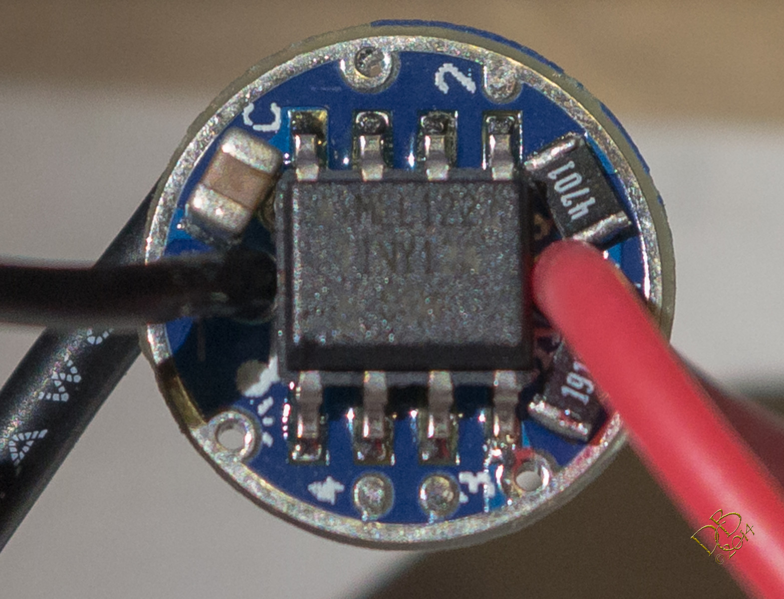
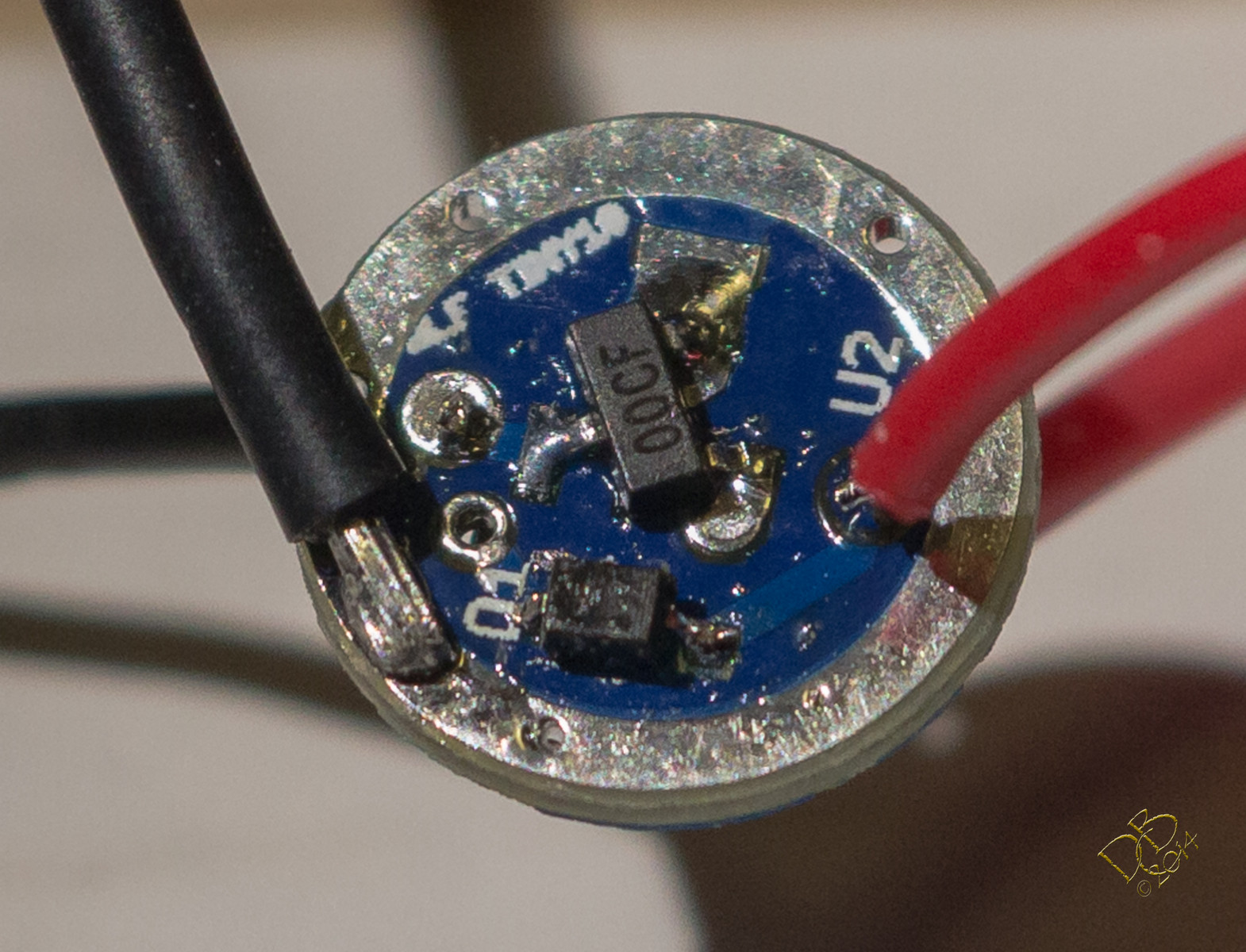
Edit: Oh yeah, the BLF 17 DD is piggybacked onto the ~24mm original driver board. This is the latest from OSHPark, with the gate resistor and pulldown resistor on the board, no finagling to get everything on there. Loaded with the STAR firmware, 4 levels plus a moon that isn’t engaged at the moment. Working great! Love these drivers! (and the power they bring to the table) My 2 year old NOVAE 32650 protected cells don’t care for this driver, however, and I had one trip the protection circuit…a first for me from any cell.
I also have that hangup about my light getting dimmer as I use it. Plus a few other hangups about DD drivers.
I don’t really understand how the driver from “Step 8” works though. Can someone break it down for me a little? Is there a name for that thing that I can use to search for an explanation?
Another linear driver with PWM may not really get me excited. Eliminating PWM and having constant current would be really nice. :heart_eyes:
In terms of MCU, my vote is for the ATiny85. That gives Arduino folks enough room to write a short program and gives our resident gurus enough space to write a long program. And it’s got a temp sensor, although maybe 25/45/85 all have that? The cost difference is <$0.50. Beyond the Arduino angle all of this is probably academic if they’ve all got temp sensors. The stacked footprints texaspyro described should physically allow all of these MCUs.
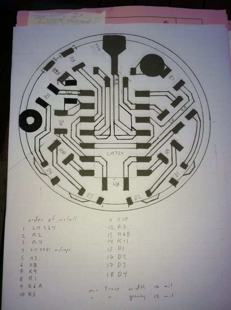
About 18 months ago I tried to learn eagle in order to build The board above but got stymied trying to figure out custom pad layout and had other things jump the front seat. Since then my laptop has become too unreliable to work on and I just haven’t had the motivation to get back to it. It’s a 4-led battery voltage monitor that I was trying to make single sided. I already have several of the LM327 IC’s along with sets of smd color LEDs (0805) and all I need now are the various R’s and boards to populate. I would be happy to mail out sets of what I have to anyone wanting one if we can get the board done. No bread boarding or testing of any kind has been done. If you read through the thread you’ll see that I just pulled that circuit from the net and made a few changes to lower the current draw.
It may not seem like it, but I am lazy. If you give me a schematic (can be hand drawn) and a list of the parts plus your dimensional* and layout requirements**, I'll get the PCB created no worries.
* Max size, pads for anything etc.
** Where do you want the LEDs? In a ring, straight line, random, etc.
I read through the thread again and seem to have either forgotten much if what I had learned then. This
Is the schematic the drawing above is based on. All the resistors and 4 SMD LEDs are 0805. The IC’s. are LM324 quad op amp and LD2981 voltage regulator.
The LEDs are laid out across the bottom edge as D1-D4 but maybe it should also have an reverse polarity diode.
2 capacitors were recommended across the input and output pins of the voltage regulator and when I used the LD2981 on a 105C I mounted them on the ic pins and might have to do that again here.
I’ll have to recheck the drawing against the schematic to see what changes I made to replace D1 with the voltage regulator and how I determined what value R to replace the pot with. Drjones suggested a 4 color led instead which should be possible with the same layout. Board size was to be 17 mm single sided to minimize thickness and since it needs both + and - it would be nice if it could stack the ground vias of a 105C with a through hole solder pad for input +.
I don’t consider this a finished design but just where I stopped so I’m open to suggestions for how it might be improved. In other words, I wouldn’t waste time in eagle just yet.
OK. I need an actual part number for the opamp. Saying it's a quad LM324 op amp doesn't really narrow it down as that's a type of op amp, not a particular model. I'll see what I can find still. Just a note...fitting 15 0805 sized plus the op amp and the LD2981 on one side of a 17mm board will be tricky. This is where we are at space wise and that's without the opamp:
Note I have not included a ground ring on the top or bottom side. Do you want one? How thick?
Question - why have you replaced D1 with the voltage regulator? Surely a zener is going to be much simpler?
I’ll be home again this evening and will get the part #.
The drawing in post724 is to scale. It was trying to create custom pads/sizes in eagle that pulled me up short.
I used the voltage regulator because I had just finished work on getting a 105C to drive 3 XML in series from 12V and back then the Zener mod was not well known and the MTG was not yet much used.
DrJones has already designed a board that does was this board can do plus much more so at this point this a bit of little and late.
I have a question about the irlm 2502 FET’s. They are spec’d at 4.2A, does that mean they’re a lot less powerful than the 70N02’s? I only have one light the 15DD will fit directly in so I was planning to use them for piggybacking onto the host lights driver board. For high draw builds should I only use them piggybacked running the host driver’s FET or will the tiny 2502’s run over spec?
Unrelated question- does anyone have a pic of a Tiny10 built with a 2505 (or similar) FET instead of 7135’s?
The 2502 is smaller and won’t pass the current that the larger FETs will so if you need more than 4A then yes you should use a larger one. I think Werner popped a few pushing them beyond spec. They were chosen to fit the board and match likely available current and heat sinking in a 14500 size host.
Dbcstm did that mod with the Tiny10 so he might have a pic. I know it can fit but will take some tweaking to get the G/D/S connections done and I found it necessary to put a 100-200 ohm resistor between the pwm pin of the mcu and the gate pin of the 2502. The easiest way to do this is to use the resistor as a jumper.
This shows one way and you probably don’t need the 10k resistor.
Dale got away without the resistor but when I mounted the FET on a 105C board it was needed to obtain stable mode switching. Also, others have experienced inconsistent behavior from one board to another so I would assume the gate resistor but try it first without. Higher drive current also seems to promote irregular behavior.
I can't recall if I have posted these previously, but here are two 7135 Slave Boards designed to be stacked on top of existing 17mm and 20mm boards. This reduces the need to stack chips.
If you had a 17mm Nanjg board could you run an 8 chip output thru this one…as in run the LED + and LED - from the Nanjg thru the outputs and run the wire from this board to the LED, kind of like an inline booster (well as long as you tied the PWM from the boards together)? Or is that how it already works?
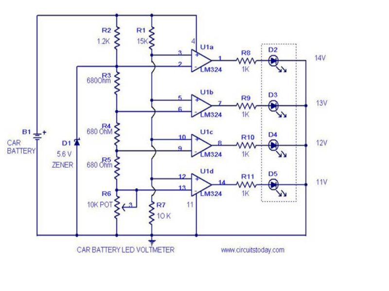 Is the schematic the drawing above is based on. All the resistors and 4 SMD LEDs are 0805. The IC’s. are LM324 quad op amp and LD2981 voltage regulator.