Not with an unmodified STAR_off_time firmware.
As I see it, you’re already running dual PWM by utilizing the single chip for moon. To select a second mode to also use that chip would maybe take a 3rd PWM channel? And available pins on the MCU are scarce? Or is it for a totally different reason?
Totally different reason. It’s all just software limitations. JonnyC’s method of controlling the two PWM signals together is fairly straightforward, easy to implement, and easy to understand.
The method used in STAR_off_time and STAR_on_time is simply to draw a line in the sand, say for example at 40/255.
|
Firmware mode level: |
Primary PWM out: |
Alt PWM out: |
|
255 |
255 |
255 |
|
200 |
200 |
200 |
|
100 |
100 |
100 |
|
45 |
45 |
45 |
|
35 |
0 |
35 |
|
9 |
0 |
9 |
We only maintain one “PWM/mode level” variable (0-255), but we have two outputs. Various features like stepdown & rampdown manipulate that variable directly. Workarounds can be implemented to get 255/255 out of our ALT PWM output and 0/255 out of our primary PWM output at the same time, but they’d potentially behave badly during stepdown and things. A full rewrite is a lot of work and doesn’t seem to get us a lot.
ok stupid question: which pad is LED- and which is + ?
Positive is the pad close to the LVP components on the other side or you can use the via that touches R1 and C1 that’s almost in the center of the board.
Just built one an hour ago. ![]()
so the large pad with the via is positive?
I can’t get it to work. The only thing I can think of is that my diode doesn’t have a line on it, so I’m not sure which way to orient it, however I’ve already tried it both directions. Is it possible I bought the wrong diodes?


You have both LED leads hooked up to positive.
If you take a close look at the OSH Park images (zoom in if you need to, I do) you’ll see that:
- The 7135’s all dump into thick traces which terminate on the pads next to the Zener, this is LED-.
- The central via is attached to a pour which extends over diagonally to the other circular pad, this is LED+.
Ignore all the little horizontal lines, these are just rendering artifacts.
In order to figure out which way the via diode goes, use “diode test” on your meter. This may be the same as continuity test (with the beeping).
- One way will show a number on the meter (forward voltage of the diode).
- The other way will show no number.
Once you find which way shows a number, make note of which end of the diode your red lead was attached to. That pin goes to BAT+, the other pin on the diode goes towards the line/arrow/etc on the PCB.
EDIT: Struck where I mistakenly wrote “via” rather than “diode”.
Ok I switched my LED- wire and sure enough… I feel like an idiot. First impression: the lower moon is SO NICE compared to the qlite.
.
It’s going to take some thinking for me to understand the diode test part.
Better to learn by doing here. Your DMM has a diode test marked with a diode symbol. You may test the diodes either in circuit or out of circuit, it won’t matter in this case. Seeing the behavior will help you understand.
Low moon over Texas. With this one I just built powering a triple Nichia, moon shows .345 in the lightbox. Turbo is 1042 lumens. What a range! That’s with 12 chips at 4.57A from a PanPF.
Nice Wight! ![]()
Edit: Did I just admit to building a light within emitter specs? Shhhhhhh…….
Sounds like fun. ![]()
What settings did you use?
![]()
#define MODE_MOON 3 // Can comment out to remove mode, but should be set through soldering stars
#define MODE_LOW 14 // Can comment out to remove mode
#define MODE_MED 39 // Can comment out to remove mode
#define MODE_HIGH 90 // Can comment out to remove mode
#define MODE_TURBO 255 // Can comment out to remove mode
#define MODE_TURBO_LOW 140 // Level turbo ramps down to if turbo enabled
#define TURBO_TIMEOUT 240 // How many WTD ticks before before dropping down.
Mode memory is on, essentially the base UI since I was having issues with the changes I made. I even went to a standard 1912 R1. Works. Works well. This is a special light and is even more so now. This one was made especially for me and I’m honored. Loving it, loving it’s output, am thankful to be a member of BLF.
Great bunch of guys here and it’s very much appreciated how friendly and helpful everyone is.
(ironically, mis-spelling great gave me greta…what’s up with that?) ![]()
Thanks DBCstm. It’s interesting that 3/255 on a single 7135 can light up a triple Nichia.
Easily. I go down to a phase correct PWM level of 1 with the 350mA chips, and it will light up a triple Nichia/XP-G2/XP-L. With the 380mA chips I usually use 2 (some won't light up or aren't stable at 1), and with 2x chips on that channel I also use 2.
Ok, I tried this on one of my diodes, and I get 0.2V? My Diodes say “41” on them. It gives a reading with the positive lead on the “4” end. So the large end of the arrow/triangle on the PCB is the positive side? So on this board the “1” end of the diode would go on the pad closest to the mcu? The driver should not function if it was backwards, correct?
Nice! Thanks for the info.
That all sounds accurate.
I see that I had a typo on the post you quoted. I’ve edited that now.
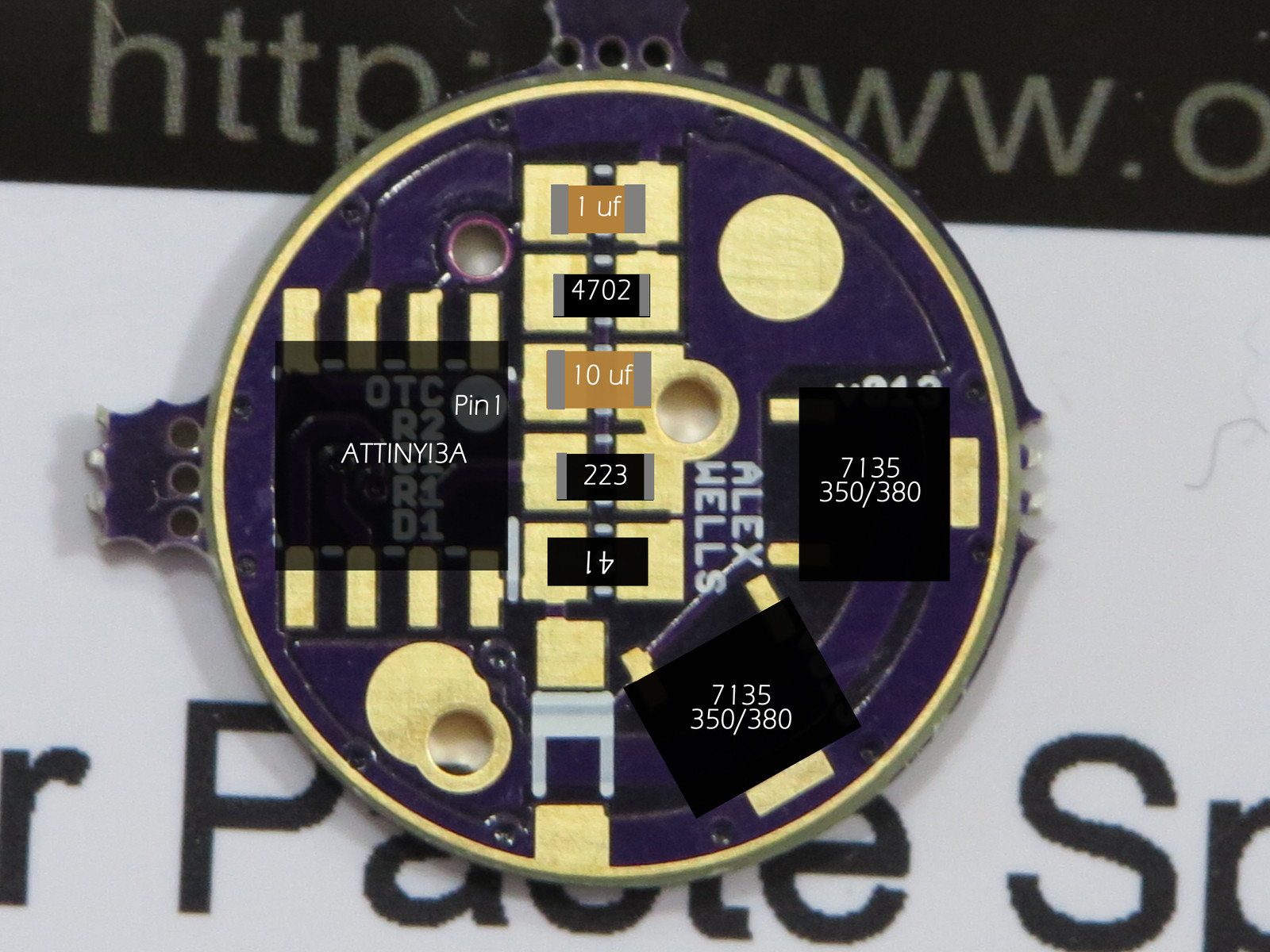
Edited with all the components…
Thanks Dale. That’s not the direction I had it initially, but I swapped it before wight informed me of my other glaring mistake. Now that I know what the arrow means, I shouldn’t have any issues with future drivers.