Man, this is really slick. I just swapped out the driver in the Eagle Eye BLF light with a 105C and was wishing for more clearance around the bottom side. Now granted it looks like FT is going with a 105D (managed to see that thread) that would solve that, but this is so much prettier and actually being able to implement dual-pwm would be nice :) Awesome work!
Looks like Oshpark sent my order to the fabricator two days ago, so I reckon I’ll have them in hand in about a week to 10 days at the most.
While I’ve got everything I need to edit and flash firmware… I haven’t actually ever flashed an attiny before. I’m pretty confident I’ll be able to do the flashing itself with the USBasp, cable and breakout board I have…. but I have absolutely no idea what changes to make to the firmware, or if changes even need to be made, or how to make those changes. Is there a crash-course explanation on how firmware works and how to (or how not to) edit it anywhere?
I’m pretty psyched about the dual PWM and can’t wait to try it out. As far as my goal for the UI, I’m hoping for L-M-H with memory and a turbo stepdown after 120 seconds… So nothing too complicated I think. Will probably do off-time mode memory as well if I get around to ordering some capacitors.
Awesome! Always cool to see new people give it a shot. Unfortunately there's no guide to editing the firmware other than reading the comments in the code. Most of it is pretty easy to understand, but things like turbo timing might not be obvious at first just because we added customizations of the time between "ticks", so it's not as simple as setting the TURBO_TIMEOUT variable to "120 seconds". Because of this I actually just pushed changes to the code that only changes the initial declarations of variables so that a 120 second turbo timeout is possible just with one variable change, and gives an easy way to change the code if you want more than 120 seconds. I highly suggest the turbo ramp down instead of step down. You can even say "after 30 seconds, start ramping down to a preset level" (granted this requires calculating how long it will take to ramp down based on the "ticks" timing). Makes for a nice smooth transition that usually causes me to go, "is it even ramping down?!", or "wow, twice the current might not really be worth it" as my eyes can't really tell that it ramped down.
It's late, I'm rambling. If you have any questions certainly post up in the main STAR thread.
JonnyC’s response covers what I was going to say, other than the point that you should get around to purchasing offtime caps. That is 100% worthwhile.
I forgot to say thanks, so: Thanks!
I think the current design looks super-usable, so I’m pleased. I can’t wait to get some in hand and see how it really plays out.
Thanks guys for your help. A generous member is sending me a handful of capacitors in the mail. I’ll still likely be ordering some as I have a feeling I’ll like off-time way better than on-time, but this way I’ll have some in time to stick on my order of PZL boards when they arrive.
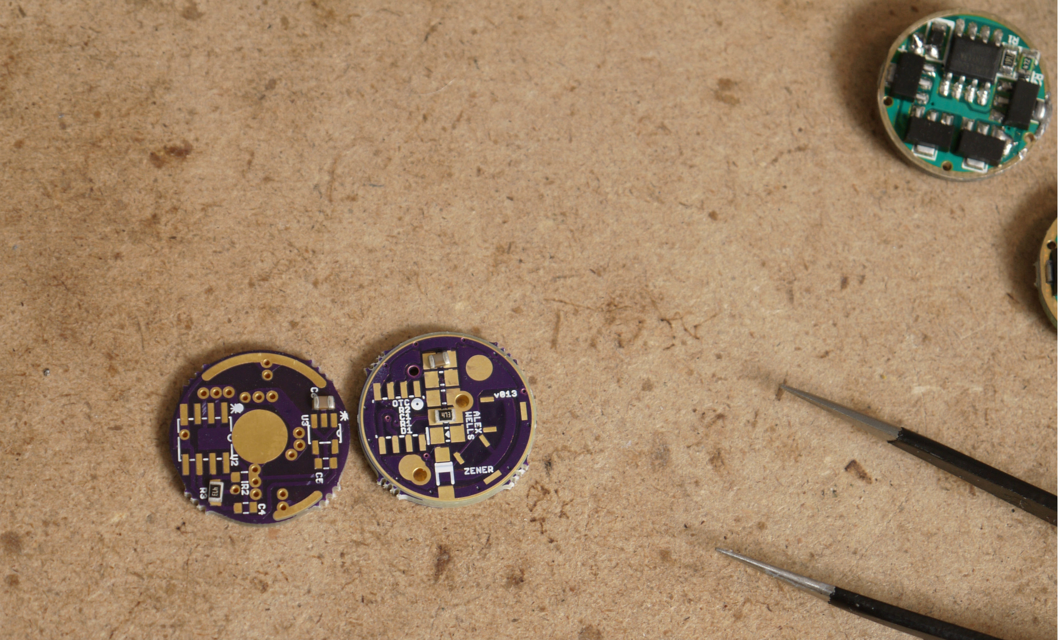
This is how your boards should look. If they don’t look like this, please post up a picture. Specifically, look out for an improperly sized solder pad for the BAT- contact.
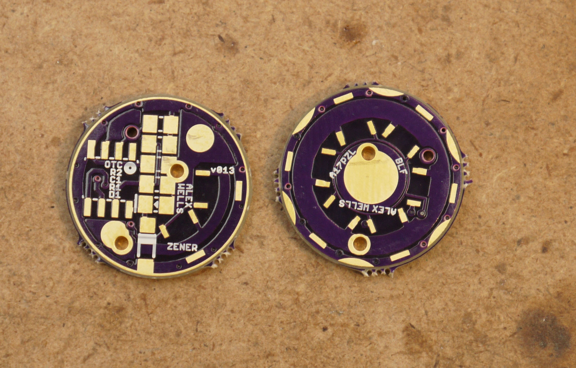
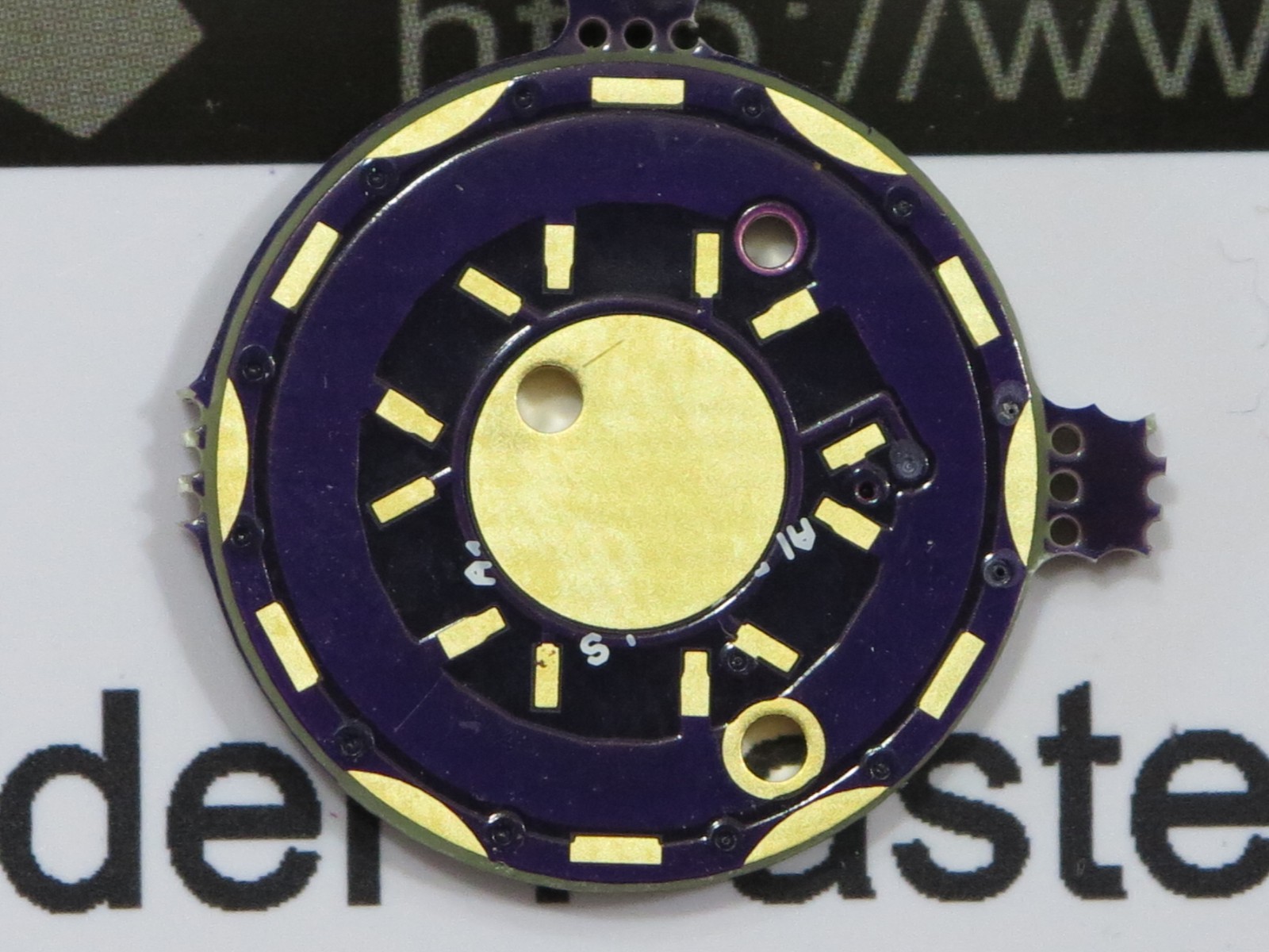
The front of mine are fine, the back has too large an exposed pad and the text is mostly gone because of it.
Other than aesthetics, are there any practical differences between this and RMM’s moonlight special?
Assuming you start with an assembled driver and use it as intended? No.
For the purposes of building one or using special features, several things jump out:
- My driver should be much easier to assemble. Looking at the images will show you why, but mostly it’s because component spacing is more generous and all solder pads are much larger. (Including those for the LED wires.)
- RMM’s driver uses the traditional and potentially more ‘correct’ location for C1. On current FET drivers we’ve abandoned this placement of C1. For the most part this isn’t relevant and makes no difference one way or another. The one scenario where it matters is that RMM’s Moonlight Special v2 is almost certainly unable to control a piggybacked FET on an extra output (PB4) for a ‘big turbo’.
- My driver provides a decently large pad (larger than where you solder LED- on a Nanjg-105c) for PB4. This can be either an input or an output. Take a look at some of the discussion in the STAR firmware thread for more info, but the idea of using an input for temperature throttling is being worked on a little.
- The current revision of RMM’s driver still uses Mattaus’s skinny GND ring - easier to damage.
- The current revision of RMM’s driver is likely to pull 7135’s outwards during reflow. That’s why I added the scalloped GND ring on mine. You’ll note that there is always a solder dam to help hold my 7135’s in place.
- I think I’ve got bigger traces, but it just doesn’t matter.
- RMM’s driver exposes “Star 3” and “Star 4” on the bottom for use either as an offtime cap location or setting up modes or with a momentary switch. My driver does not expose Star 3 on the bottom but does expose Star 4 with a covered via which you can scrape. Normally Star 4 is used for offtime on the top. The via is large enough to pass a stripped wire through without scraping in case that’s what you want to do: you just solder the wire onto the OTC pad on top. Really mine is setup specifically to optimize it’s options for use without stars while RMM’s is setup to make the best potential use of stars.
- RMM’s driver has traces for both PWM signals available on top. Mine does not. With that in mind, RMM’s driver would be better for driving a secondary LED with PWM after cutting traces and doing some scraping.
Mostly piddly stuff in the end.
Your first bullet point was enough for me!
RMM offers a build service, Wight does NOT. ![]() (Do you?)
(Do you?)
RMM’s drivers are designed for RMM to use in his own builds, he’s not trying to make it easy for the masses only making it do what he wants it to. This is the critical difference and of course for us on the end both drivers work exceedingly well. Those large pads are indeed appreciated by those of us that drink too much coffee and are too lazy to take the large stock tip off the soldering iron. ![]()
Both of you guys are over the top and greatly appreciated. ![]()
In regards to the tip, I tried using a needle tip for 7135 stacks, and it wouldn’t hold the heat, so I’m back to a medium chisel now. I guess I’m in good company.
You’re right DBCstm, that’s certainly one major difference! I encourage everyone to build their own. ![]() :-p
:-p ![]()
![]() The only drivers I currently offer to build are the drivers in my Lux-Pro kit.
The only drivers I currently offer to build are the drivers in my Lux-Pro kit.
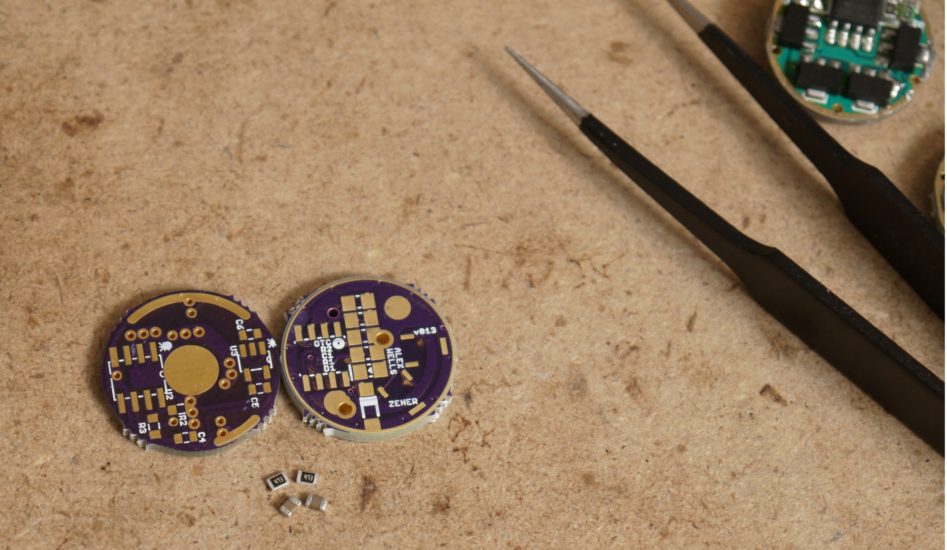
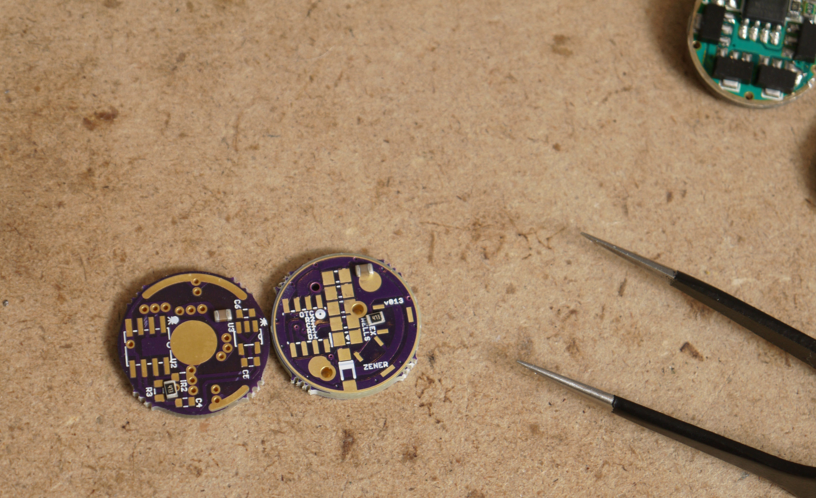
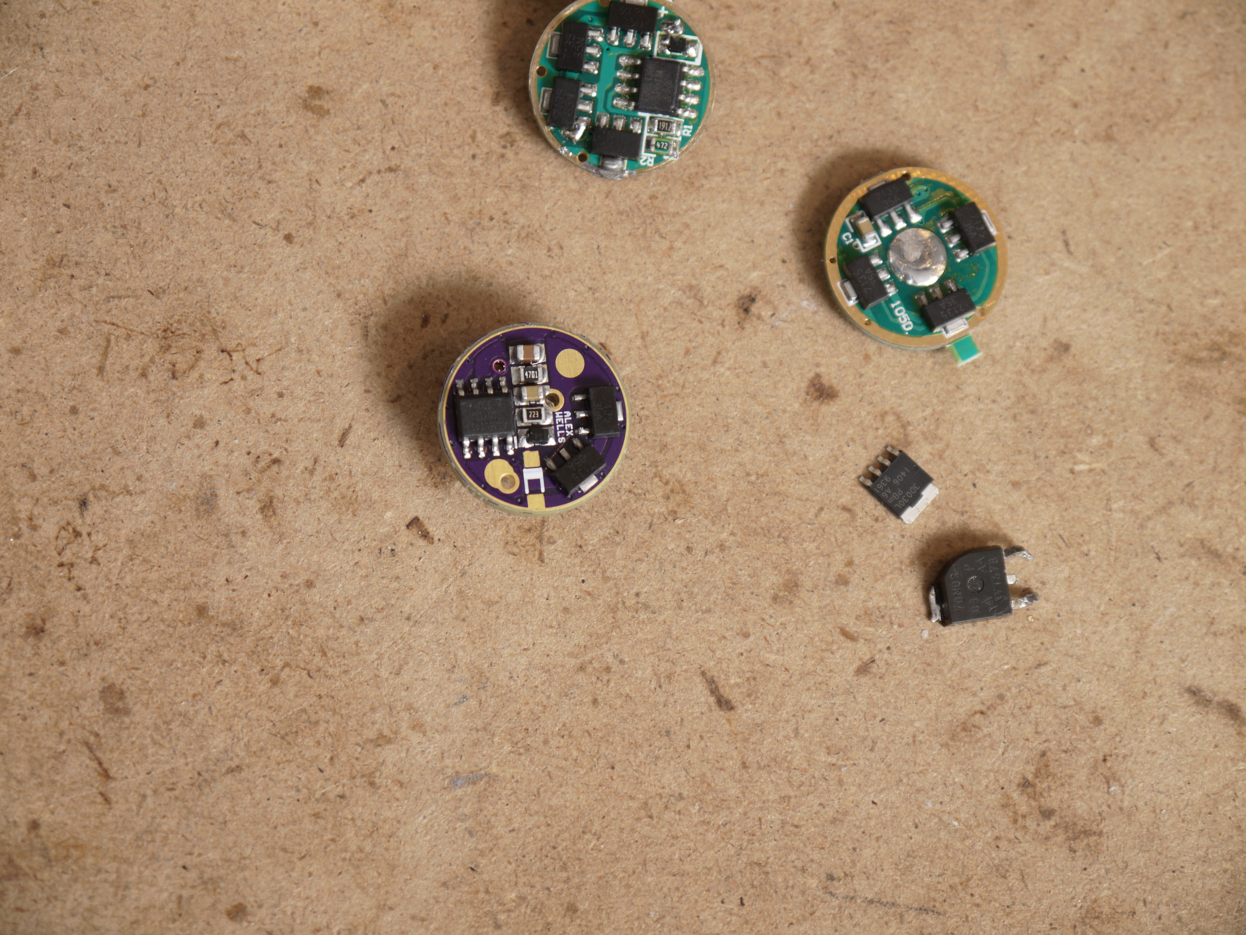
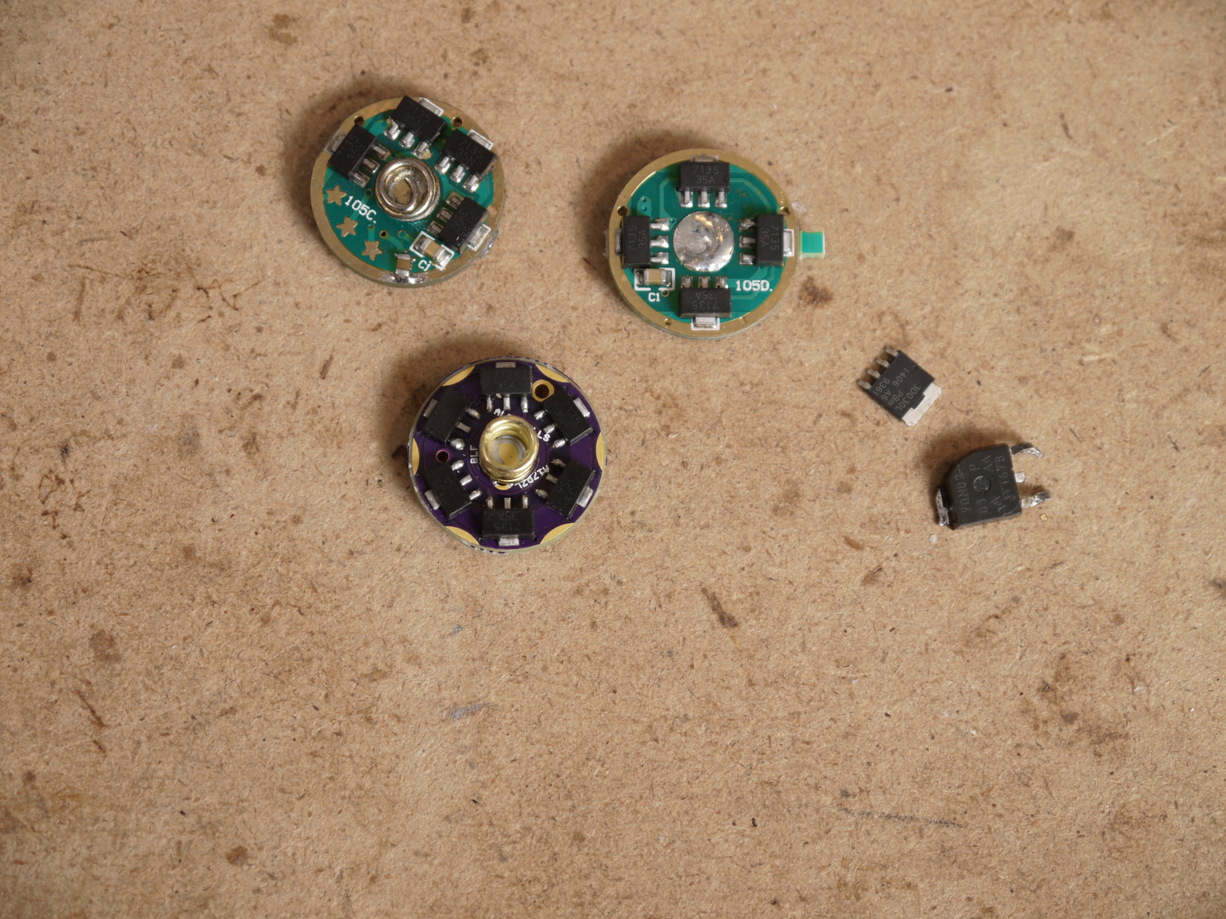
To underscore that point: These 3 pictures show my A17PZL driver (which uses full size 0805 footprints) on the right and a different driver which employs 0603 footprints on the left. As you can see I’ve got a pair of 0805 sized components for each driver and I proceed to lay them onto the pads. 0603 pads are usable for 0805 (and there is a specification for using that sized pads for 0805, it’s not just some hack). The difference is that hand soldering, inspection, and rework are all more difficult with the smaller pads. Click for big versions.
Here are some pictures showing an assembled driver. Click for larger versions:


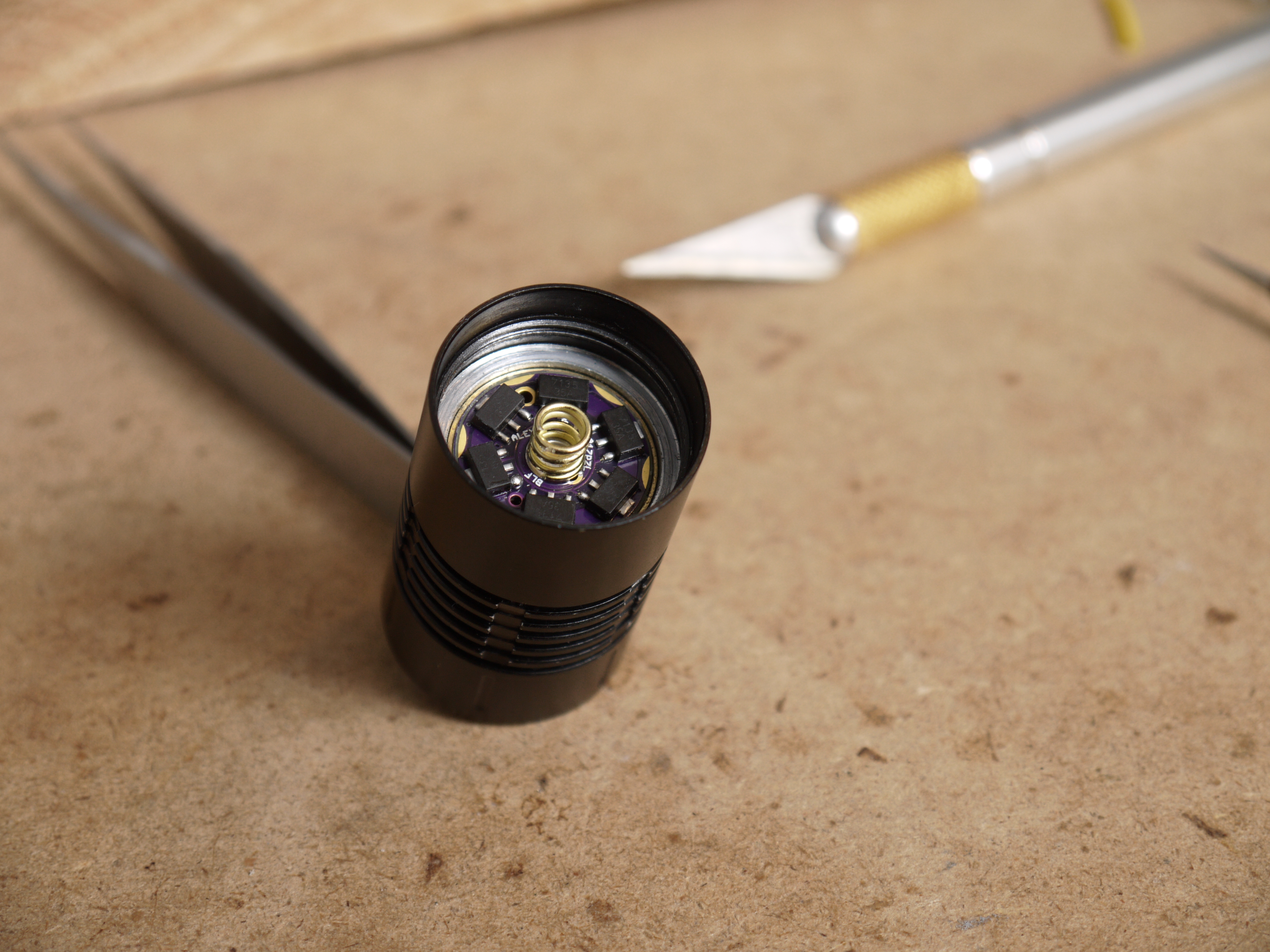
AW for the win!
I like that PZL driver, works great and looks really cool installed.
I do believe that’s the first time I’ve ever put 7135’s on a board that didn’t have 7135’s under em! lol (to make myself feel at home, I did that as well. ![]() )
)
Thanks DBCstm!
I felt like I was leaving something out and sure enough I was. I forgot to mention that these were actually pics of the second A17PZL I’ve seen assembled. DBCstm got started a bit earlier than I did! ![]()
These look so awesome. I got my boards from Oshpark about a week ago… hoping to assemble a few in the next couple of days. Can’t wait to try them out… and also to get my feet wet on messing with firmware.
One question… any issue with using 1912 resistors (like from a standard 105C or qlite)? Noticed you used some with slightly higher value above. I’m far from an EE so I have very little understanding of what the resistors even do for the MCU. Is the difference something I need to account for with the voltage monitoring parameters in the firmware?
Thanks grantman321. The 19.1k resistor can work fine with tweaked parameters, it’s not a problem. 22k is cheap and easy (it functions at least passably with the stock values). Take a look at the comment section at the top of STAR_off_time.c to see a description of how those resistors are used and a summary of the math. Understand that we’ve moved the input for the voltage divider from the back of the diode to BAT+, so the “~.25 v drop from the protection diode” which JonnyC mentions is now gone. I just use a voltage divider calculator (this one).
I go on a bit more on the subject over here, and probably some other places too: Oshpark Projects (#917)
Just a question what if my mode is 10mA, 350mA, and 2.8A, can i use the mode 10mA and 350ma on that single 7135?