Dang a pic or two would be so helpful ![]()
Edit: Pic is the A6, Not X6
Is this the culprit? Maybe Mike can confirm USA warehouse had a deal a few weeks ago. I got a bunch for $3.63ea
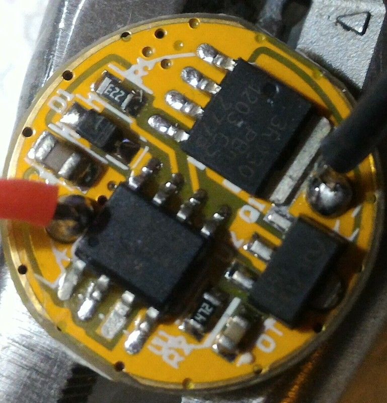
That is the BLF A6.
This is the BLF X6/X5…

… the difference is that the BLF X6 / X5 has R3 (471 = 470Ω), next to the red wire.
Sorry bout that. Had the A6 in my mind whole time reading the thread.
But thank you, learned how to ID them if I get some mixed.
The A6 driver you’ve got there , is from the old batch , the same that was used in Blf A6.
In the x6/x5 driver the “R3” is just the bleeder resistor.
Latest A6 drivers i have , are on X6/X5 boards , with place for the bleeder resistor.
New BLF X6 driver at the left, old one at the right:

They changed the layout.
R1 / R2 marking is wrong , but the resistors are in the right place.
Massive solder.
Just use your iron with a small chisel tip set to the highest temp. Heat each leg one at a time while gently prying up with a small slotted screwdriver. As soon as the solder melts that leg will pop up and you can move to the next one. Install the new mcu one leg at a time as well. Heat each leg till it squishes down into the solder from the old mcu that should still be on the board. If there is not enough solder left on the board, add a little bubble of solder first. For both removing and replacing use LOTS of flux with a little bit of wet solder on your tip. If your tip gets oxidize from the high temps, cool it down, wipe it of, and add a bit of new solder to wet the tip. At least this is what I’ve found to work well. Trying to get all legs at once is hard to do without destroying the rest of the board. That said, you can do all legs of one side at once by using a hot tip and laying it on the side. Slide it back and forth while lightly prying the mcu with a small slotted screwdriver and slide the iron back and forth till that side of the mcu pops up. But again, FLUX FLUX FLUX!
Thank you guys for the pictures and the hints for removing the driver! :-) I'll hope for the best and will try to flash them and if not, Reichelt.de should deliver new Attiny25 to my doorstep in a few days...
Hi all,
I may have found yet another solution that does not include soldering: high-voltage programming.
I've soldered the circuit at http://www.rickety.us/2010/03/arduino-avr-high-voltage-serial-programmer/ on a stripboard and tried with an Attiny13. The fuses where changed back the way I told the Arduino to. :-)
What the circuit does is provide an interface for an Arduino which flashes the fuses in the Attiny13 while pulling RST up to 12V at specific times (aka high voltage programming). In the comment section of the website, there is also the code to erase any lockbits. That should get the Attiny25 on the driver going. :-) Only downside: the chip will be erased (at least when erasing the lockbits) -- nothing to worry about because we do have the FW we want to flash.
I hope this helps.
Best regards
Thanks for the info. I knew the more expensive Atmel programming devices have this 12 V option to reset fuses, but never tried it. I’m curious if it also works in-circuit with the BLF X6 (there is a capacitor at Pin 2/clock). Should require a changed programming clip connection (clock pin is not required with USBASP). I have Arduinos but I’m not sure if it’s worth the effort compared to replacing the Attiny with a new one for the few new drivers I received.
The USBASP is not used during resetting the fuse: The Arduino does nothing but erasing and (re)writing the fuses -- no flashing. The clip I have uses all eight connections and is separate from my programmer (a avrisp2 clone).
If you do have a spare Attiny lying around it might not be worth the effort. But since I don't have any and had the Arduino, I thought I'd give it a try. Guess I'll have to see if it really works in-place with the driver, but I sure hope so.
Best regards
Just wanted to let you guys know how it went: resetting the fuses and flashing the FW worked. However, not without removing C1 first.
As Flashy Mike had already assumed, the 12V-programming does NOT work with the C1 in place. I tried a few times with a brand new board and the Arduino kept on telling that the fuses are "FF" -- an indicator that it does not work (it does not mean that the fuses actually are set to "FF" though...). Just remove the capacitor (don't lose it! ;-) use the Arduino so reset the fuses, solder C1 again and you're good to go. Flashing worked instantly and the FW I flashed worked on first try, too. Yay.
Something does really annoy me, though:. The C1 capacitor seems to be extremely prone to temperature drift. A medium click with a cold lamp needs a press of roughly 3s. When the light is hot to the touch (but doesn't burn your skin obviously), a medium press needs to be about 0.3s long -- that is one tenth of the initial time!
Most probably I'll try a higher quality capacitor. What do you guys think about this one https://www.reichelt.de/Vielschicht-SMD-G0805-High-Cap/X7R-G0805-1-0-25/3/index.html?ACTION=3&GROUPID=4339&ARTICLE=89730 (I hope that posting this link is OK, otherwise please let me know so I can remove it...)?!
Best regards
I just reset the fuses on another driver and remembered to write down the fuses...
Low: D2
High: 5E
Which shows why programming cannot work: This sets RSTDISBL and thus, the Attiny cannot be reset externally which is needed for programming though.
A quick question .
I want to ask , how you can indicate the problem ? It shows a programming error or the driver doesn’t opperate in the right way ?
AVRDUDE reports “target doesn’t answer”.
thanks .
Because the latest A6 driver i have from banggood , it isn’t showing any error in Avrdude but it operates as a single mode driver… Flashed it a lot of times but nothing . I’ll probably change the attiny .
Some of my own fet/fet+1 drivers i flashed yesterday they work ok.
OTC might be wrong value, not properly connected, shortcut or damaged.
If it starts in highest mode, LED- might be shortcut to BATT- or casing.
FYI:
I built a hig voltage serial resetter today which is able to reset bricked Attinys (for another purpose: New Convoy 7135x8 driver - mcu not programmable!) and was able to reset the mcu in my newer BLF X6 drivers. The resetter reported factory fuse settings of low=0xD2 and high=0x5E in all drivers which means Reset-Pin has been disabled. And without this pin programming with USBASP doesn’t work.