This discussion is getting very interesting, in a very civil manner I might add.
Good and informative info, thoughts, & suggestions. :+1:
.
My thoughts align more with Yokiamy, djozz, & many others as far as heat sinking, heat path, & heat transfer goes. Make it right the first time. It does not cost more to leave metal, it is actually a bit less machining; so cost is slightly decreased.
So make it in the best possible way as far as shedding heat. No valid reason not to.
There is a bit of disconnect as I’m not working directly with the engineers. I go through a middle person (Cissy? I guess I should ask their name) who is a translator and not familiar with all the technical stuff.
So I have to simplify and use pictures as best I can to get the ideas across. It is difficult.
Unfortunately, they are not able to switch to a one piece head design because: “one piece head is very different for us due to machine knife and CNC time.” So it will still be a two piece design. They are going to extend the threads between the two which can only help heat transfer.
On a more positive note, they said they can make some changes to improve the heat flow.
I sent my latest set of ideas to them:
They said they can do ideas 1、2、4、5, but not 6. “It’s hard for us to make 6. It’s hard to explain, but if we can do this, we will. But if we need to purchase new machine or too much machine work time, I’m sorry that’s too much to handle.”
So here is the updated “design”.
They are still concerned about keeping the light balanced and not too heavy in the head, but if you have some more ideas to improve the design please post them up.
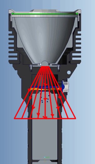
This is not how heat transfer happens, there is no linear projection, no guided cone.
Heat sinks by conduction towards cooler material in proportion to how much cooler it is and how good a thermal conductor it is.
Now in this case we have one uniform material, aluminium, so the thermal conductor is identical. Other materials in the design are to all practical purposes irrelevant.
So heat will flow through the cross-section as if the aluminium were a raised concrete surface and you were pouring water on to it from the position of the LED. Heat cannot escape to the air very fast, so consider all the outside edges to have a retaining wall of fine mesh through which the water flows slowly.
The aim is to keep the water from rising close to the LED.
The greater the length of outside edge the faster the water can escape. Fins good!
The higher the water rises at any point the faster it pushes through the mesh at that point.
The narrower any passages are, the less effective the loss through them, as there will be a build-up of water height at the source side to push through the narrow passage, and thus the height at the fin side is reduced, and the less water pushes through the mesh around the fins.
I think this is the most effective way to visualise it. I can’t produce a diagram like that though.
The beefing up of the area near the led will help, also as a simple heatsink that will extend a turbotime.
Something else, but it will change the shape of the head and thus the aestetics: if the fins at 2) are enlarged outwards as wide as the fins at 1) you will end up with a couple of actual decent fins that are reachable for the heat because of the now thicker material in between led and fins (let’s hope that the threading does not spoil it too much). (and not rounded like the plunger option that most did not like, but straight, more Luckysun D80 style)
About the balance, I do not see where to remove a lot of material in the head, so the most efficient way to compensate the balance is by adding weight to the other side: how about a cool massive SS tailcap that will also match nicely with the SS bezel? :sunglasses:
No. It is not proof that there is “very high” thermal resistance between the LED and the fins.
It is proof that, unfortunately, thermal path to the switch is rather good though.
The fins and head will heat up more slowly because they are, at their extremes, much further from the emitter, have greater mass, and can shed more heat more quickly.
I also tried extending the fins just a little bit more. Which you see on the bottom part.
Then I saw a need to add more material near the threads and I combined it with the medium length fins.
I came up with this:
I don’t know, maybe this would work without changing the head shape too much? Sofirn may not want to alter the head shape. The picture in the post below keeps the head shape Sofirn likes.
Here’s a few tweaks. I put all the changes on the top. The bottom is stock. You can see there is pretty good heat flow paths. The further away you get from the heat source, the thinner the material gets.
Number 7 and 8 are the new changes. Number 7 just extends the fins all the way around the back side of the switch. Number 8 just adds a bit extra material near the threads. The shape of the head stays the same.
Wouldn’t it be better to have the cross section with the threads further away not closer? Its a hard one because its not a single piece head. To many drawings going on right now lol.
I’m not really understanding you. In order to get more heat transfer across the threads, they are adding more threads (from 6 threads to 10 threads) on the lower part of the head. This gives more points of contact.
Is this what you are refering to?
As far as too many drawings, you can never have enough! Lol
One more idea, probably not manufacturable for them but maybe worth asking…
Can they move the threads to around or behind the shelf, so the driver/switch assembly is the screwed-in part and everything from the shelf forward is one piece?