That sounds good, 200-300k probably isn’t a bad middle of the road option with enough leeway either side to tweak with firmware.
You don’t want to go too far with a standard resistor value and run out of tweaking headroom in either direction.
I had a 360k, 430k, and 470k -- went with the 470k. Much better - I can now move it away bout 4 cm's quickly and will mode change. It's still quick but I think will be usable once mounted back in the light.
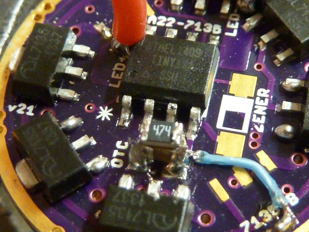
here's the final look. The cap got pretty messy looking. That little wisp of solder off the 7135 ground pin I removed after I saw it in this pic. The blue wire (wire wrap 30 AWG) was my attempt to speculate on a better ground but it did nothing. I use that blue wire for e-switch's - works well, very thin - think it's Teflon coated.
Update: I got the light assembled and really like the responsiveness of mode changing. Slightly delayed hold and the mode sticks, normal quick 1/2 clicks and it changes modes. It's difficult to get it to change modes on full clicks - too much time. The 470k resistor works out well.
This F13 is with 4.9A of 7135's, XM-L2 S6 7D3 (warm) on a 20mm Noctigon, UCLp lens, 22 AWG wires, springs bypassed, measured on a KK 26700 @4.21v 4.96A tail, 833 lumens @start, 802 lumens @30 secs. Doesn't drop much at all in the 1st 30 secs, and I think part of the reason is the 26700 cell with it's high capacity (bout 5300 mAh).
The lumens is obviously low, but it is an S6 bin, and from djozz's tests, I believe my meter will measure NW and WW tints low. Both MtnE and ILLUMN had these warm LED's bare and cheap a while back, so I picked up two of them. Weird how various tints come and go - it's all subject to availability by CREE I suppose...
Ah, some good collaboration here. Thanks Cereal_killer / LinusHofmann / Tom E for posting details.
… I fired up Eagle to take a closer look at the layout and started doing a little work. I was dismayed to find that the design was completely broken and could not function… until I realized that Tom E had posted photos of v21 and there I was editing v020. Oops!
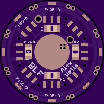
Here’s a slightly revised board. I included a pulldown resistor. It can’t [physically] be populated at the same time as the Zener. From Tom E’s earlier posts it sounds like 470k+ is a good place to start, maybe much higher such as 1.0M-Ohm depending on your needs.
v022

 OSH Park ~
As we can see, the R-OTC sits inside the Zener’s area:

Great work, I’ll have to order a couple of these boards. Started filing down a spacer to fit a standard 17mm driver but this is a much neater solution.
Cheers
Will these fit into the stock F13 with the retaining ring?
Yes - how mine looks. The ring sits directly on the 7135's - think that was discussed as being ok in the past, maybe another thread. I use a little NO-OX-ID (illumn.com no-ox-id) from Craig & co at Illum on the ground ring (and 7135 tabs) of the MCU side of the board, just in case it helps. Also use it on the threads of the retaining ring. I'm a little scared to crank that retaining ring too tight, but you certainly want it tightly fit though.
I should have taken a pic of the spring side - think I went with an upside down spring because I wanted a long one to be close to the length of the stock one. It works great -- love the 26700 cells from Richard for this light (mtnelectronics.com KK26700 5000).
Just as a heads up, the last two I used need a copper braid ground “tab”. The driver pocket now has an angle, so the driver ground did not touch the pocket at all. Only the 7135’s were touching.
bdiddle, could you post a picture?
Really? This would make life much easier in so many ways. I’d been scared of shorting something out by having a retaining ring pressing down on the 7135s (and whatever else might be nearby …)
I sure don’t see a problem with it….
Careful - on this board its ok, but standard Nanjg's have other parts besides 7135's on the backside (like a cap) that will be a problem.. Pic's here: intl-outdoor.com-nanjg-105c.
The 7135’s are the tallest parts by a wide margin. If the retaining ring lands on those everything else should be safe.
I can’t get a good shot that is in focus ![]()
One of these that I built has no LVP kicking in. I verified the resistors read ~22k and ~4.7K, reflowed them, reflashed the tiny13, and swapped the tiny13. Still no LVP kicking.
My other drivers built the same way and flashed with the same STAR OT program have LVP kicking in just fine.
:~
- What version did you build?
- Measure the voltage on that MCU pin.
- You must populate the 7135 next to R2.
Ah……The 7135 next to R2 was empty. Doh.
…just so I can build this driver. Hopefully, I’ll be flashing by then, but if not, can one of you zap the MCU for me?
I’m just getting back into modding after taking the last 5 years off—hey, my flashlights still work.
Got a fresh solder paste syringe in the fridge.
Got a 30X stereo microscope.
Got a toaster oven, controlled by a PID, that is awesome for reflowing.
Thank you everyone who has made this possible. I used to make my own PCBs from scratch, but lost the equipment when I got bought out.
It’s a lot better to be able to flash your own because you may need to tweak the offtime and LVP values. Please see this thread: Hoop - Guide: how to flash a NANJG / Qlite driver with custom firmware
RMM will probably flash whatever you need on an MCU for one or two USD, with shipping around $2 USD: http://www.mtnelectronics.com/index.php?route=product/product&product_id=311