Ducks do waddle around in places I wouldn't. If a bad aroma is the problem this could be it. I to do have sinus problems being spring here. Maybe that's why Dale, FMC and I are posting? Maybe everyone that has clear sinuses are staying away? Whatever the reason your work is beyond reproach.
another work of art ![]()
Yep, I have the tail end of the 'flu.
HEY! I’m watching this thread… sometimes. 0:)
I wish I were going to finish my contest light in time, but I’m fairly certain now that I’m not. Life happened and stole all my time away. I hope to still finish it some day. :weary:
Great work on this light. It looks beautiful! I’m looking forward to seeing it finished!
More stuff
What was your reason for using AA for securing the MCPCB to the pill rather than soldering them together?
It's a rainy day and I'm back reading this thread.
There's two things that strike me: 1) what a beautiful pieces can you make with mainly just hand tools (and a bit of spinning around), the quality looks immaculate, 2)I see sooo much work, a few hours just to file the fins down and then another few hours on the same fins to make that even better. I wish I had the patience for that  .
.
David- The pill is soldered together rather than brazed so a second solder step might have wrecked the first step. I couldn’t braze again because of how the threads were cut into a sleeve with a seam rather than a continuous cylinder. I still might have done it anyway but a 3am decided not to.
Jos- Thanks, a lot of work does go into this but I have the same issues as Justin with things being not quite straight, square, even, etc. When spinning the parts wobble to make one dizzy. I still like it even with the imperfections but they’re there. At least some skills are still improving so I cling to the hope that I’ll get it right one day.
The light is beautiful as expected! YOU ARE TOUGH! Gooooooood Grrriiiieeeeeffff!
I look at all that effort and just wonder if I could do that. I looked at every picture....multiple times.... sit here a minute... went straight out and hugged my lathe!!! I mean hugged that rascal. Might even have given it a short smack on the lips!!
The fins are beautiful... as good as they come. I like it all!
Beautiful work Rufus... the whole thing is outstanding... and I love the wood!!! Send it right on over here and I'll take good care of it!!  TL
TL
So the driver went together ok? When this is finished does it come with its own glass fronted wooden framed hanger for the wall? Its to nice to use.
Looks pretty good from a few kays away doesn’t it. ![]() You take real good care of those lathes or they might just pick up their dainty little feet and leave you for a more appreciative owner. I won’t know if the driver works until the Fujik cures. The soldering went well and that’s as much as I’ll commit to for now. The one thing I really don’t like about P60’s or other small reflector based lights is the lack of adequate clearance for the solder pads. The lip on the base lands squarely across the middle of the wire pad so this morning I covered the led hole with a bit of tape and trimmed the lip back to ~11 mm.
You take real good care of those lathes or they might just pick up their dainty little feet and leave you for a more appreciative owner. I won’t know if the driver works until the Fujik cures. The soldering went well and that’s as much as I’ll commit to for now. The one thing I really don’t like about P60’s or other small reflector based lights is the lack of adequate clearance for the solder pads. The lip on the base lands squarely across the middle of the wire pad so this morning I covered the led hole with a bit of tape and trimmed the lip back to ~11 mm. 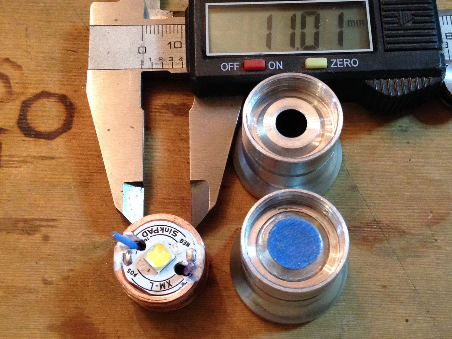 The pad to pad distance is 11.5 mm and with the base sitting on a clear isolator and the wires toward the outer edge it should just work. Also frosted the XHP50 dome as per djozz’s method to deal with the dark spot.
I was thinking it might be cool to have a more rustic version in knotty pine and black.
As to where it ends up it’s not my decision but I’m open to mislabeling the shipment for a reasonable gratuity.
I thought it might be something like that, but I don’t know for sure without asking! ![]()
Since you mentioned it, I’ve been thinking about that solder pad issue. What if… what if one were to drill the correct sized hole right through the pad on the star, down to the driver, such that the silicone insulated wire would JUST fit. With the wire cut off square one could then solder across the exposed end of the wire to the pad, or just cover it with solder. It would be as minimal a rise above the star as one could possibly get and shouldn’t be all that difficult to accomplish.
So, what am I missing? I mean, if it works this way you could simply lay an insulation disc over it and there would be no short. Right? Sounds too easy, gotta be missing something….
No, you’re not missing anything, that’s how Cutters’ triple and quad mcpcb’s for the cute-3/4 are done including the new T-pad DTP boards. They work but are a pain to line up the wires if you can’t access the backside. They have insulated sleeves pressed into it with a solder pads over the top. They actually have them spaced for 2-pin headers.
Did some more assembly. I’ll post pics later so you’ll have something to wake up to and enjoy over your coffee. It’s not running yet but length is sooo tight I wanted to make sure I could screw the tail cap on. Is it too late to join the comp sos I can win and keep it? One things for sure, ain’t another one on eBay or anywhere else.
Some more new pics added in post 1(just realized I’ve been saying post two for awhile). Fwiw, the total surface area of the fins is 10 x 2 x pi x (18.5^2- 12.5^2) + 10 x pi x 37 x .8 = ~12,600 square millimeters which sounds like a lot more than it is but is still about 20 square inches. A lot to cram into 16 mm length.
You know what you have to do to finish this light
Solder the led wires and add a spring bypass.
The problem with p60 reflectors and pills is the circular cavity in the reflector is partially taken up by the rim of the pill and the solder pads on 16 mm mcpcb’s are moved in to where they come under the flat of the reflector base. Were I to do this again I might use a 20 mm star turned down to the un threaded pill OD then solder and thread them as one. Then there’s no lip and the solder pad can be closer to the perimeter.